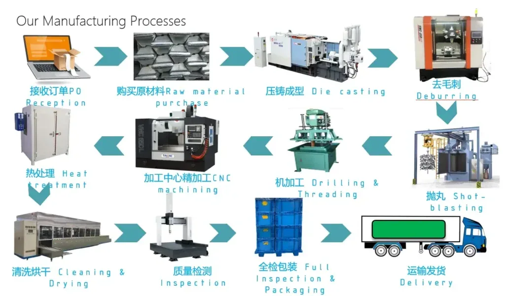
Inside the HKX Die Casting Process
Every aluminum die casting project at HKX moves through seven controlled stages, from the first DFM review to the last carton on the pallet. All seven run inside our 2,000 m² plant in Beilun, Ningbo, so a drawing never leaves our control between tooling and shipment. What follows is the actual sequence, the machines each stage uses, and the tolerances we hold at each hand-off. For the one-paragraph answer to what this process actually is, see what the HKX die casting process is.
Stage 1 — DFM Review and Mold Design
A STEP, IGES or DWG file arrives and goes straight to a design review, not to a quote. Our engineers check draft angle, wall thickness, parting line placement, ejector pin locations, gate position and thermal hot spots. Minimum wall for a sound aluminum casting is 1.0–1.5 mm depending on projected area, and any wall below that is flagged before tooling starts. Filling and solidification are then simulated to predict air entrapment, shrinkage porosity and weld lines. The output is a mold 3D, a 2D assembly drawing and a written DFM report listing every change we recommend and why. Customers approve that report before a single block of steel is cut.
Stage 2 — Tooling Fabrication
Molds are cut from H13 (SKD61) tool steel, hardened to HRC 46–52. The sequence is CNC roughing, stress relief, finish machining, CNC EDM for deep ribs and sharp corners, then wire EDM for the parting line and inserts. Slides, lifters and the ejector system are fitted and spotted by hand. A T1 trial shot follows, and the first parts go to the CMM for a full dimensional layout against the drawing. Tooling correction happens here, while the steel is still easy to move — not after production has started.
Stage 3 — High-Pressure Die Casting
Production runs on 2500T, 800T, 500T and 280T cold-chamber machines. Aluminum alloy is melted and held at 680–720 °C for ADC12 and A380, degassed and checked with a spectrometer before every shift. Die temperature is held at 180–250 °C with oil or water circuits, and gate velocity runs 30–50 m/s with intensification pressure of 60–100 MPa. Cycle time lands between 60 and 120 seconds depending on wall section and part weight. Shot profiles are recorded, so a parameter drift shows up as data rather than as a defect three weeks later.
Stage 4 — Trimming and Deburring
Parts go from the die to a 100-ton trim press with a dedicated trim die that removes runners, overflows and biscuit in one stroke. Hand deburring follows on edges the trim die cannot reach, then shot blasting where the surface finish calls for it. Trimming is where a poorly designed die shows up as bent or cracked parts, so trim dies are built alongside the mold, not after it.
Stage 5 — CNC Machining
As-cast features hold die casting tolerances. Anything tighter moves to machining: 3-axis and 4-axis CNC centers plus CNC lathes, running on fixtures designed for the part rather than generic vises. Bearing bores, sealing faces, mounting datums and threaded holes are cut here, typically to ±0.05 mm and to ±0.02 mm where a drawing demands it. Machining and casting are quoted as one scope, so the tolerance stack is decided once instead of argued over between two suppliers. The measuring and workholding tools that decide whether a machined feature actually lands in tolerance are covered in our machinist tools guide.
Stage 6 — Surface Finishing
Finishing options include shot blasting, vibratory deburring, anodizing, electrophoresis, powder coating, painting and electroplating. The finish is chosen against the service environment — an outdoor lamp housing and an internal gearbox cover do not need the same treatment. Masking for machined faces and threads is set up at this stage so a coating never lands where a bearing has to fit.
Stage 7 — Final Inspection and Packing
Final inspection combines CMM layout, X-ray for internal porosity, spectrometer for chemistry, hardness testing and leak testing where the part seals a fluid or gas. Sampling follows the control plan; safety-critical automotive features are checked 100%. Parts are then packed with EPE foam, cartoned and palletized for export, with the inspection report and material certificate travelling with the shipment.
Machine Tonnage and What Each Size Fits
Tonnage is not a marketing number — it decides which parts are economic to cast and which ones need a different process. Across our 50+ machines, the working ranges look like this:
| Machine | Typical shot weight | Parts that fit well |
|---|---|---|
| 280T | up to ~2.5 kg | Small brackets, lamp holders, connector housings, heat sink sections |
| 500T | up to ~5 kg | Motor end caps, controller enclosures, pump covers, instrument housings |
| 800T | up to ~9 kg | Gearbox casings, pump bodies, motor housings, structural brackets |
| 2500T | up to ~25 kg | Large structural parts, EV motor shells, transmission housings |
Annual capacity runs to roughly 5,000 tons. If a part sits near the top of a tonnage band, we will say so at quotation — running a heavy part on an undersized machine costs the customer money in scrap rate, not just cycle time.
Tolerances We Hold
As-cast tolerances follow the two published tiers used across the industry. NADCA Standard is about ±0.25 mm (±0.010 in) on the first inch; NADCA Precision is about ±0.05 mm (±0.002 in), with roughly ±0.025 mm added for each additional inch. European and Asian drawings usually reference ISO 8062-3 instead, where aluminum high-pressure die casting lands at CT5 to CT7, and CT4 to CT6 is achievable on critical features. As-cast surface roughness on die-contact faces is typically Ra 1.6–3.2 µm. Any dimension crossing the parting line gains extra allowance and needs its own review. Full detail is in our die casting tolerances guide.
Typical Parts and Production Data
A few representative jobs show how the stages line up in practice:
- EV motor shell, ADC12, 800T. 6 mm body wall, 3 mm hollow flange, 1.5° draft on the pre-cast bore. Cycle time around 90 seconds, mold life targeted at 100,000 shots with a spare cavity insert. Automotive programs like this run under our automotive die casting quality control process, with PPAP and batch traceability from the first shot.
- Gearbox casing, A380, 800T plus CNC. As-cast surfaces left at CT6, bearing bores machined to ±0.05 mm, leak tested at 30 Pa or better for three seconds. Machinery housings of this type are covered in more detail on the general machinery die casting page.
- Lamp holder, ADC12, 280T. High-volume, single-cavity, shot-blasted and powder coated, packed in bulk for a lighting OEM.
- Industrial chassis, A380, 500T. Large flat panel with ribs; flatness controlled by fixture design in machining rather than by tightening the casting tolerance.
Where to Start
Send a 3D model and the drawing, and the first thing you get back is a DFM report, not a price. From there the sequence above runs on a fixed schedule with a named engineer on your project. If you are still choosing a process, our service overview explains where die casting beats sand casting and where it does not; if material choice is open, start with the aluminum alloy guide.
Finishing options applied after trimming are listed on the surface finishes page. To start a quotation, send drawings through the 快速查询表. Tolerance, tooling ownership and lead time questions are answered in our die casting FAQ.