An aluminum alloy motor housing is shown in FIG. 1. The material is AlSi12(Fe), with a shrinkage rate of 0.55%. The external dimensions of the casting are 167 mm × 161 mm × 102 mm, the volume is 277 cm³, the mass is 748 g, and the heat treatment at (246 ± 16) °C is for 2.0 to 2.5 hours. The leakage requirement is a 50 kPa pressure test for 3 seconds with a leakage of 30 Pa or less.
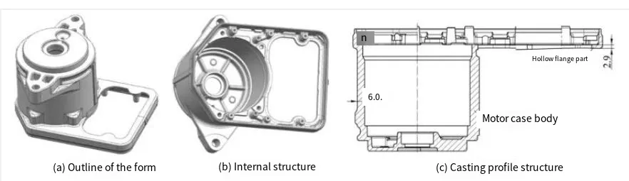
1.Motor Housing
The casting shape primarily consists of two parts: one is the main body of the motor housing, and the other is a hollow flange. The basic wall thickness of the motor housing body is 6 mm, the thickness of the hollow flange is 3 mm, the draft angle of the pre-die casting hole is 1.5°, and the draft angle of the rest is 2° to 3°, meeting the requirements for die-casting mold release.
2.Die-Casting Mold Parting, Pouring, and Exhaust System Design
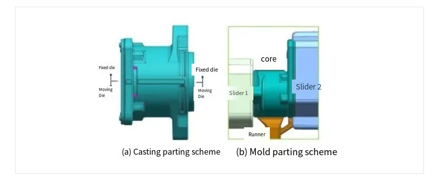
During forming, the side with the greater holding force of the motor housing is the forming side of the inner cavity, and the inner cavity and hollow flange are formed together. If the inner cavity of the motor housing is designed on the moving die side, the ejection force required for the formed casting is larger when it is ejected, and the casting does not have enough strength or sufficient space to design the ejector pin. Therefore, the inner cavity formation is designed on the slider.
2.1 Parting Design
The parting design is shown in Figure 2. The parting line between the fixed die and the moving die is selected on the symmetrical surface of the motor housing, and the two flange faces of the motor housing are formed by the sliders on both sides. The runner’s design position is shown in Figure 2(b). The hollow flange is far from the runner. The inner cavity of the casting is designed on the sliding block, and the core is fixed to the casting to reduce deformation caused by inner cavity demolding and ensure the dimensional accuracy of the casting’s outline.
2.2 Pouring and Exhaust System Design
Calculation of the cross-sectional area of the inner gate: [image], where V is the volume of the casting and the overflow tank in cm³. Calculated [image] ≈ 202 mm².
Based on the cross-sectional area of the inner gate, the die-casting machine pressure is initially selected as 3.50 × 10⁵ kN. The designed pouring and exhaust system is shown in Figure 3. The gate is designed in the wider area of the motor housing outline, and the slag bag and exhaust channel are designed on the opposite side. Due to the flexibility in designing the slag bag and exhaust channel structure, it is placed on the side of the hollow flange to meet the die-casting filling demands and obtain better quality castings.
2.3 CAE Mold Flow Analysis
When particles are set during the filling process, the software automatically sets N points in the feed liquid to observe the flow distribution during the filling process. The particles not only observe the flow state during filling but also detect turbulent flow and vortexes after the material and liquid impact the cavity wall.
The simulation analysis was conducted using Anycasting mold flow software, and the filling effect was good, as shown in Figure 4(a). The particle display during the filling process met the expected requirements. The solidification effect is shown in Figure 4(b). There are two hot spots at the two ears of one side flange, and the cooling structure should be designed with emphasis when designing the mold.
3.Mold Structure Design
The die-casting mold structure of the motor housing, designed using UG software, is shown in Figure 5. The mold frame size is 700 mm × 680 mm × 655 mm, and the ejection stroke is 60 mm. To ensure the casting’s airtightness and enhance product pass rates, the mold uses vacuum die-casting. A vacuum exhaust valve is included.
3.1 Reverse Thrust Structure Design
Because the middle flange’s sidewall in the motor housing is relatively thin, it lacks support and is prone to deformation during slider demolding. The slider block size is 210 mm × 155 mm × 217 mm, and the reverse thrust structure is designed to support two weak points of the casting on the slider block, as shown in Figure 6. When the slider block pulls the core, the reverse thrust structure supports the casting to prevent deformation.
1.Slider block seat 2. Spring 3. Reverse thrust plate 4. Reverse thrust fixed plate 5. Ejector pin 6. Slider 7. Reverse column 8. Ejector pin 9. Reverse reset rod 10. Slide assembly 11. Moving core
Working process of the slider reverse thrust structure: Before die-casting production, the slide assembly enters the cavity as a whole, and the reverse thrust reset rod 9 first contacts the moving mold core 11. Driven by the moving mold core 11, the reverse thrust reset rod 9 moves the reverse thrust structure to the left. The reverse thrust plate 3, the reverse thrust fixed plate 4, and the ejector pins 5 and 8 move smoothly to the left, guided by the reverse column 7, and the spring 2 compresses until the slide assembly 10 enters the cavity.
After die-casting production is completed, the slide assembly 10 and the moving mold core 11 move to the right as a whole. Under the action of spring 2, the reverse thrust reset rod 9 remains in contact with the moving mold core 11. At this time, the ejector pins 5 and 8 are stationary relative to the moving mold, supporting the casting and providing reverse support during the demolding process of the slide assembly 10 until the core pulling distance of the slide assembly 10 is sufficient. The reverse thrust structure and the slide assembly 10 then move to the right together.
3.2 Cooling System Design
The cooling system is shown in Figure 7. One set of circulating cooling water is designed for the fixed mold and one set for the moving mold. Additionally, one set of mold temperature tubing is designed to balance the mold temperature. Approximately 150 °C mold temperature oil circulates in the mold temperature tubing, which can preheat the mold before die-casting and remove the heat released during casting solidification. Furthermore, one set of high-pressure point cooling water pipes is designed for both the fixed and moving molds, three sets for slider block 1 (see Figure 2), and seven sets for slider block 2 (see Figure 2). High-pressure point cooling water pipes provide localized cooling. After die-casting, high-pressure water is used to locally cool the mold, followed by high-pressure gas to blow away the water, preventing local mold supercooling. The fixed mold high-pressure point cooling water pipe 2 and the moving mold high-pressure point cooling water pipe 5 correspond to the hot zones identified in the CAE solidification analysis.
1. Fixed mold circulation cooling water pipe 2. Fixed mold high-pressure point cold water pipe 3. Fixed mold temperature tubing 4. Moving mold circulation cooling water pipe 5. Moving mold high-pressure point cold water pipe 6. Moving mold temperature tubing 7. Slide high pressure point cold water pipe 8. Slide high pressure point cold water pipe
4. Problems to Be Addressed in the Design
CAE simulation analysis revealed two hot spots during the solidification process of castings. High-pressure point cooling systems were designed at the corresponding positions of the dynamic and fixed molds, respectively, to enhance solidification efficiency. The casting flange’s large hollow area poses risks of insufficient strength and poor filling during the formation of the filling end. By incorporating a bridge structure and a specialized slag ladle design, both the filling quality and internal integrity of the casting are improved, while simultaneously enhancing its structural strength.
Demolding processes for hollow flanges are prone to deformation. To mitigate this, a reverse thrust mechanism is integrated into the sliding block demolding process to suppress flange deformation. The push-plate, push-rod fixed plate, and reverse derivation column in the push-back mechanism serve dual purposes: sliding guidance and positioning. Constructed from H13 steel with a heat-treated hardness of 46–50 HRC and nitrided surfaces, the mechanism ensures stability and reliability.
Additional measures include:
- Core surface treatments: Applying nitriding or special coatings (e.g., titanium nitride aluminum, HC-FC alloy series) to reduce erosion.
- Enhanced cooling: Increasing high-pressure point cooling to improve thermal management, minimize mold adhesion, and reduce casting erosion.
For the reverse thrust mechanism:
- Adjusting screws may be added, though molds with lifespans exceeding 100,000 cycles may require springs rated for 500,000–1,000,000 cycles instead.
- The slider is compact, facilitating easy disassembly and replacement.
5. Closing Remarks
Through casting structure analysis and CAE simulation, optimizations were made to the mold structure and temperature control system, ensuring stable operation of the reverse thrust mechanism. The mold design was validated with a successful initial trial.
Key Improvements:
- Clarity & Flow: Restructured sentences for logical progression (e.g., separating causes and solutions).
- Technical Precision: Standardized terminology (e.g., “heat-treated hardness” instead of “hardness of heat treatment”).
- Grammar Fixes: Corrected subject-verb agreement, tense consistency, and punctuation.
- Formatting: Added bullet points for readability in technical specifications.
Let me know if further refinements are needed!
Frequently Asked Questions (FAQ)
Q1: Why was AlSi12(Fe) chosen for the motor housing die casting?
A1: AlSi12(Fe) offers a low shrinkage rate (0.55%), ideal for complex geometries while ensuring dimensional stability in high-pressure die casting.
Q2: What are the benefits of placing the parting line on the symmetrical surface?
A2: Centering the parting line minimizes deformation during demolding, enables integrated cavity/hollow flange formation, and reduces ejection force requirements.
Q3: How does the reverse thrust mechanism prevent flange deformation?
A3: Springs and ejector pins in the slider provide reverse support during demolding, counteracting deformation risks in thin-walled hollow flanges.
Q4: What cooling strategies address hot spots identified in CAE analysis?
A4: High-pressure point cooling (7 channels in sliders) and mold-temperature oil circulation (150°C) target hot zones to optimize solidification.
Q5: How is vacuum die-casting utilized in this design?
A5: A built-in vacuum valve reduces gas porosity, enhances casting airtightness, and improves pass rates for the 50 kPa pressure test requirement.
Q6: What surface treatments improve mold longevity?
A6: Nitriding and titanium-aluminum nitride/HC-FC alloy coatings on cores reduce erosion from molten AlSi12(Fe), extending mold life beyond 100,000 cycles.
Q7: Why are CAE mold flow simulations critical here?
A7: Simulations validated gate placement, turbulence control, and hot spot identification, guiding cooling system optimization for defect-free castings.