The Two Tiers Every Casting Drawing Should Name
Picture the last drawing you sent out for quotation. Somewhere on it there is a dimension. Maybe it is a bearing bore, a sealing face, or a mounting datum. Next to it, someone typed ±0.05 mm. It looks harmless. It is not. In high pressure die casting (HPDC), that one number decides a lot. It decides whether your part runs at a stable cost for years. It also decides whether you end up in a standing argument with your supplier.
Die casting tolerances are the allowed drift between the size you draw and the size you measure. They exist for a simple reason. Molten aluminum does not behave like a machined billet. Metal shrinks as it freezes. The die halves flex under injection pressure. Cores deflect. The tool wears a little on every shot. You cannot remove that drift. You can only decide how much of it you accept. You also decide how much you will pay to shrink it.
This guide is for buyers, project engineers, and quality managers. If you source aluminum castings, it is for you. We will cover the two tolerance tiers the industry uses. We will cover the numbers that matter, feature by feature. We will look at three trends changing what foundries can hold in 2026. Then we will cover the design habits that keep cost down. By the end, you should be able to read any drawing. You will know which dimensions are realistic as-cast. You will also know which ones belong on a machining step.
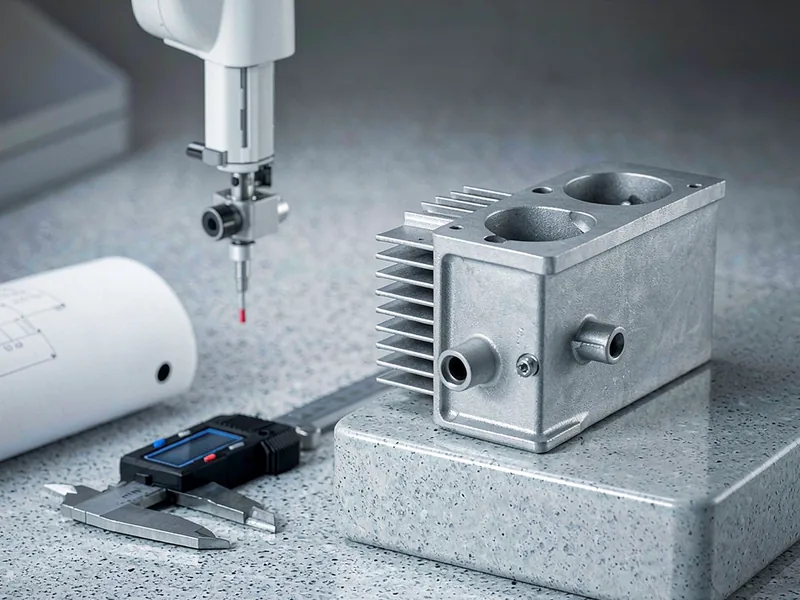
Key Takeaways
- Die casting tolerances come in two published tiers. NADCA Standard is about ±0.010 in (±0.25 mm) on the first inch. NADCA Precision is about ±0.002 in (±0.05 mm). Add ±0.001 in for each extra inch.
- ISO 8062-3 covers the same ground in metric markets. It uses CT grades. Aluminum HPDC normally lands between CT4 and CT6, never CT1.
- Any dimension that crosses the parting line gains extra allowance. It also gains a separate shift allowance.
- Draft angle is not negotiable. Plan 1°–2° on inside walls and 0.5°–1° on outside walls.
- Precision die casting on every feature adds 10 to 30 percent to part price. Keep it for mating, sealing, and datum features.
- Tighter than ±0.05 mm on a raw casting is a CNC job. It is not a casting job.
North American buyers work from the NADCA Product Specification Standards. The North American Die Casting Association publishes them. The document splits results into Standard and Precision. That split has nothing to do with the alloy or the part shape. It shows how much care goes into the tool, the process, and the inspection. Standard is what a well-run shop holds in normal production. Normal die maintenance applies. Normal sampling applies. Precision is what the same shop holds with more effort. The tool is tighter. Die service intervals are shorter. Measurement happens in-line. The shop also accepts more scrap.
The base numbers are simple. Take a linear dimension up to one inch. Measure inside a single die half. NADCA tolerance standards put Standard at about ±0.010 in (±0.25 mm). Precision is about ±0.002 in (±0.05 mm). Add roughly ±0.001 in for each extra inch. A five-inch feature held to Precision works out to ±0.006 in. European and Asian supply chains usually reference ISO 8062-3:2023 instead. It expresses the same idea through Casting Tolerance grades. They run from CT1 (tightest) to CT16 (loosest). Aluminum and magnesium HPDC typically sits at CT5 to CT7. CT4 to CT6 is achievable on well-balanced tooling. Zinc casts tighter, generally CT4 to CT6. It melts at a far lower temperature, so it stresses the die less. CT6 and NADCA Standard are close cousins. They are not identical twins. Always verify the die casting tolerances your drawing implies. Do not assume a grade transfers cleanly.
Here is what most buyers get wrong. Standard and Precision are not competing products. You do not pick one from a catalog. They are two answers to one question. How much variation will you tolerate, and who pays for the tighter one? Standard tolerances come with the process. They cost you nothing extra. Tighter die casting tolerances cost real money. Expect more scrap, more inspection labor, and faster tool wear. Die maintenance cycles get shorter too. Precision callouts typically add 10 to 25 percent to the piece price. On large or awkward parts, the premium runs higher. There is also a third tier. It is not a casting tier at all. If your need is tighter than about ±0.05 mm, process discipline will not save you. No raw surface will hold it. That dimension becomes a machining step. Budget stock for it. Stop asking the casting process to do a milling machine’s job.
What Each Feature Can Actually Hold
A blanket tolerance on a whole drawing causes trouble. That is how programs end up in PPAP disputes six months into production. The reason is simple. Die casting tolerances are not one number. Different features are formed by different pieces of steel. So they inherit different error stacks. A dimension inside one die half inherits cavity accuracy and shrinkage variation. That is all. A dimension spanning the parting line inherits much more. It also picks up die set alignment, clamp force deflection, and flash thickness. Cored holes add core deflection under injection pressure. That effect grows with depth-to-diameter ratio.
| Feature type | NADCA Standard | NADCA Precision | What it means on the floor |
|---|---|---|---|
| Linear dimension, first inch / 25 mm, within one die half | ±0.010 in (±0.25 mm) | ±0.002 in (±0.05 mm) | Add ±0.001 in per extra inch of length |
| Across the parting line (added to linear) | +0.012 in (+0.30 mm) | +0.005 in (+0.13 mm) | High side only — die separation only adds material |
| Moving die slide (added to linear) | +0.012 in (+0.30 mm) | +0.006 in (+0.15 mm) | Value grows with slide projected area |
| Parting line shift (added to linear) | ±0.008 in (±0.20 mm) | ±0.004 in (±0.10 mm) | Even on both sides; driven by guide pin wear and heat |
| Flatness, first 3 in / 75 mm | 0.012 in (0.30 mm) | 0.005 in (0.13 mm) | Add 0.004 in Standard or 0.002 in Precision per extra inch |
| Draft angle, inside walls | 1° to 2° | 0.5° to 1° | Inside walls need roughly twice the draft of outside walls |
| Draft angle, outside walls | 0.5° to 1° | 0.25° to 0.5° | Below Precision you risk galling and tool damage |
| Cored hole draft | 2° per side | 1° per side | Shrinkage onto the core demands extra relief |
| As-cast roughness, die-contact faces | Ra 1.6–3.2 µm typical | Not a tolerance, but it rides along with every decision | |
Summarized from published NADCA tolerance tables and industry practice. Values for these features vary with projected area — confirm the exact figure for your part.
If your supply chain spans regions, put both systems on the print. Comparing die casting tolerances across regions only works when both sides read the same units. Showing an ISO 8062-3 CT grade next to the NADCA tier saves weeks of email. A Chinese or European foundry reads CT grades natively. A North American shop reads NADCA. The metric baseline runs from ±0.14 mm at CT4 up to ±0.30 mm at CT6. That applies to sizes up to 25 mm. In the 400 to 1000 mm range, it widens to ±0.40 mm and ±1.00 mm. Real as-cast results land between those grades. Expect roughly ±0.10 to ±0.15 mm on small features. Expect ±0.40 to ±0.60 mm on large ones.
| Nominal size range (mm) | CT4 (mm) | CT6 (mm) | Typical aluminum HPDC result (mm) |
|---|---|---|---|
| Up to 25 | ±0.14 | ±0.30 | ±0.10 to ±0.15 |
| 25 to 63 | ±0.18 | ±0.40 | ±0.15 to ±0.20 |
| 63 to 160 | ±0.22 | ±0.50 | ±0.20 to ±0.30 |
| 160 to 400 | ±0.30 | ±0.70 | ±0.30 to ±0.40 |
| 400 to 1000 | ±0.40 | ±1.00 | ±0.40 to ±0.60 |
Add roughly ±0.1 to ±0.2 mm to any dimension that spans the parting line. One habit to build on top of that: anchor dimensions to datums. Do not stack ± values feature on feature. Stacked tolerances compound. Four ±0.10 mm callouts can eat 0.40 mm of budget before anyone touches the die. Datum-based dimensioning per ASME Y14.5 solves this. It tells the foundry and the CMM which surfaces govern.
Three Trends Reshaping Precision in 2026
Die casting used to compete on tonnage. Whoever had the biggest press won the structural work. That race is over for most mid-sized foundries. The competition has moved to precision, porosity, and stable size. Three trends drive it. All three affect the die casting tolerances you can ask for on a purchase order.
1. Vacuum-assisted casting and heat-treatment-free alloys are pulling as-cast tolerances tighter. Vacuum-assisted HPDC evacuates the cavity before the shot. Shops running it report porosity reductions of 60 to 80 percent. Less trapped gas means less blistering during T6 heat treatment. So structural parts can be heat treated without warping. That warping used to force a straightening operation. Alongside it sits a family of heat-treatment-free alloys. They reach usable mechanical properties without a T6 or T7 cycle. Foundries report 15 to 25 percent cost reductions on large parts. For tolerances, the second effect matters most. Remove heat treatment and you remove the distortion it introduces. As-cast windows that once needed a straightening pass are now available on a raw part.
2. Gauging moved from final inspection to the machine itself. Modern cells document 30 to 40 process parameters per shot. These include intensification pressure, die cooling flow, temperature zone by zone, vacuum level, and shot profile. Closed-loop systems adjust injection parameters within milliseconds. They read the previous shot to do it. For checking, 100 percent CMM and X-ray checking is replacing sampling. For a buyer, this changes what you should ask for. A capability study with real Cp and Cpk values is a fair request in 2026. Target your key dimensions. A PPAP submission with a full layout is fair too. The data already exists. The foundry only has to export it.
3. Tolerance allocation became a DFM negotiation instead of a drawing default. This is the biggest shift. It is cultural more than technical. Buyers are learning that die casting tolerances are an economic choice. One recent program started with a drawing with Precision on 47 separate features. After a structured DFM review, only six actually needed it. The rest were non-functional, hidden in assembly, or protected by a downstream machining step. The program re-quoted at roughly 18 percent less. Not a single part changed function. Two smaller effects ride along. Aluminum price volatility makes trial-and-error tooling too costly. So buyers front-load mold flow simulation instead of fixing defects after the die is cut. The EV push also created a two-track market. Gigacastings grab headlines. Meanwhile mid-scale foundries win hydraulic, material-handling, and heavy-equipment work. They win it with tighter size control plus integrated CNC finishing.
Standards and Further Reading
These are the primary sources behind the numbers above. All are published by associations and standards bodies, not by casting suppliers.
- NADCA Product Specification Standards for Die Castings — the North American Die Casting Association publishes the Standard and Precision tolerance tables most US and Canadian programs reference. Check this first when a supplier quotes you a tolerance: diecasting.org/PSS.
- ISO 8062-3:2023 — geometry and size rules for moulded parts. Part 3 defines the CT grades and machining allowances used across Europe and Asia. The 2023 edition replaced the 2007 version: iso.org/standard/77952.html.
- ASTM B85 — Standard Specification for Aluminum-Alloy Die Castings. It defines chemistry and mechanical property rules for A380, A360, A413, and similar alloys: astm.org.
- ASME Y14.5 — Dimensioning and Tolerancing, the reference for datum-based GD&T. Stop stacking ± callouts. Pay only for tolerance that matters. This is the standard your drawing should follow: asme.org.
How to Allocate Tolerances So You Pay Only for What Matters
Good allocation is a learnable skill. It starts with accepting one truth. The casting process has a natural accuracy band. It does not care how important your feature feels. Roughly ±0.10 to ±0.30 mm is the practical as-cast window. That applies to linear dimensions on aluminum, depending on size and position. Inside that band, accuracy is nearly free. Outside it, cost rises steeply. Most of the money buyers waste on die casting tolerances comes from one place. They pay for accuracy on features that do not need it.
So sort your dimensions into three buckets. The first is cosmetic and non-functional. Brackets, ribs, outer profiles, and non-mating surfaces belong here. Use Standard tolerance. Write it down explicitly rather than leaving it blank. The second is functional but not sealing or locating. Bosses, structural walls, and clearance features fit here. Also Standard. Route them inside a single die half wherever geometry allows. The third bucket is critical. Bearing bores, sealing faces, o-ring grooves, mounting datums, and pilot diameters belong here. These are the only features that deserve a Precision callout. Most of them should be machined to final size rather than cast. That last point is where buyers give away the most money. If a bore is machined anyway, the die casting tolerances on that bore are irrelevant. The as-cast dimension only needs to leave the right stock. Specifying casting-level accuracy on a machined feature is paying twice. You get the accuracy once.
Second, handle the parting line deliberately. Never place a key dimension across it if you can avoid it. Redesign the feature to sit inside one die half. That is almost always cheaper. The alternative is tolerancing, inspecting, and sometimes rejecting a cross-parting dimension at volume. When you truly cannot avoid it, budget the allowance. Know that it grows with projected area. Clamp force deflects the die halves by an amount proportional to area and pressure.
Third, respect the physics of cooling. Aluminum shrinks roughly 0.5 to 0.6 percent linearly on freezing. That rate is not uniform. A part with mixed 2.5 mm and 6 mm walls shrinks more in the thick section. It stays liquid longer there. So a 300 mm datum span can pick up 0.15 to 0.25 mm of spread. That is with walls of 2.5 mm and 6 mm. It happens before tooling variation even enters the picture. This is why we push uniform wall thickness early. It is a size strategy, not just a fill strategy. Finally, plan for die age. Thermal cycling slowly opens the die joint. Heat checking accumulates on the cavity. A die at 300,000 shots will not hold what it held at 5,000. Agree on wear allowances and refurbishment intervals in the supply agreement.
Cast It or Machine It?
The cleanest way to make the call is to compare two numbers. One is achievable accuracy. The other is the cost of buying it. On the casting side, accuracy is cheap. It stays cheap until you approach the process limit. On the machining side, accuracy is expensive from the first tenth of a millimeter. It gets more expensive with every setup. The crossover sits near ±0.05 mm for a raw surface. That is also the floor on die casting tolerances in production.
Below that threshold, the arithmetic changes. A Precision round gets you to roughly ±0.05 mm. A machined round gets you to ±0.02 mm or better. Single-setup five-axis work goes tighter still. It avoids setup-to-setup stack-up. So you pay for an operation. In return, you buy accuracy the casting process cannot deliver. What you should not do is split the difference. Do not buy Precision die casting tolerances on a feature that really needs machining. That produces a part that fails inspection. It produces a supplier who is technically compliant with your drawing. And it leaves you no clean exit from the argument.
Before any tooling is cut, send a DFM request with your RFQ. Ask which dimensions the foundry will hold as-cast. Ask which ones it will machine. Ask for the parting line location and the draft angle plan in writing. Those two decisions lock in most of your tolerance outcome. Ask for the CMM layout format used for first article inspection. Ask how the supplier will prove the die casting tolerances it quoted actually hold in production. Then compare replies across suppliers. A foundry that answers with specific numbers understands its own process. A foundry that replies with ±0.1 mm on everything is telling you something. Nobody looked at your drawing. Once production starts, keep the conversation on data. Request capability studies on key dimensions across the first few lots. Watch Cpk rather than individual readings. Treat drift as a process problem. Check die cooling balance, intensification pressure, and metal temperature before you reach for a drawing change. For the documents to expect on a casting program, see our guide to inspecting aluminum castings with a checklist.
If you are sourcing aluminum castings, send us the drawing. Ask for a second opinion on which dimensions can be held as-cast. Our engineering team returns capability feedback and machining stock advice. You also get a tolerance-by-tolerance breakdown before tooling begins. Reach us through our contact page. You can also read more in our overview of the high pressure die casting process and our die casting capabilities.
Frequently Asked Questions
What is the tightest tolerance die casting can hold?
The tightest practical die casting tolerances on raw as-cast aluminum land near ±0.05 mm. That applies to a short dimension inside one die half. It requires Precision process control and a well-maintained tool. Zinc reaches slightly tighter because it melts at a lower temperature. Need better than ±0.05 mm? Plan a machining step instead of fighting the process.
Why does my dimension fail inspection right at the parting line?
Because it carries more error than the rest of the part. It inherits die set alignment, clamp force deflection, flash thickness, and shift. None of those touch a dimension measured inside a single die half. Move the feature off the parting line if you can. If you cannot, budget the allowance. Then inspect it knowing which error sources stack.
How much extra does precision die casting cost?
Expect roughly 10 to 25 percent on the piece price. Large or difficult geometry costs more. The premium covers higher scrap, in-line gauging, more frequent die service, and shorter tool life. Control it the way NADCA tolerance standards intend. Limit Precision callouts to the few features that genuinely need them.
Do I need to model draft angle in my 3D file?
You do not have to model it. You do have to specify it. For aluminum, plan 1° to 2° on inside walls. Use 0.5° to 1° on outside walls. Textured or coated surfaces need more. Insufficient draft causes defects. They look like size failures but are not.
How do I verify tolerances once production is running?
Ask for a first article layout on a CMM. Then ask for capability studies on key dimensions across the first few production lots. Watch Cpk rather than individual readings. Cpk warns you about drift before rejects appear on the dock. For pressure-tight or safety-relevant parts, add X-ray or leak testing to the plan.