Draft Angles for Die Casting: Degrees by Feature & Alloy
The die casting draft angle is the taper you build into every vertical wall so the casting slides out of the die. Skip it and the part sticks, drags, or tears. The die may crack at the corner, and the whole tool needs welding before it runs again. Draft costs nothing at the drawing stage and saves a fortune at the press. This guide gives you the draft angle numbers we use on production tools, broken down by feature and alloy, plus the shrinkage and texture effects most designers miss. You will also see where you can safely reduce draft and where you cannot. Read it before you release your next aluminum die casting drawing.
Key Takeaways
- Standard die casting draft angle: 1.5° to 2° on outside walls, 2° to 3° on inside walls.
- Inside walls need more draft because the core shrinks onto the metal as it cools.
- Add 1° to 1.5° extra for deep cores, rough texture, or long slide travel.
- Draft applies to every surface in the pull direction — including holes, slots, and ribs.
- Cutting draft below 0.5° invites scuffing, die wear, and high scrap.
What Draft Angle Actually Does
Picture the die as a steel box with your part’s shape cut into it. When the casting cools, it shrinks onto the core and grips it hard. Without taper, the two surfaces lock together along their full height. The ejector pins then push a part that cannot move. Something has to give — usually the casting, sometimes the die.
Draft breaks that lock. A one or two degree taper turns a parallel grip into a sliding fit. The part releases in the first few millimeters of travel, then falls free. Draft angle is not cosmetic. It is the release mechanism.
Alloy shrinkage sets how much grip you fight. Aluminum alloys shrink about 0.5 to 0.7 percent as they solidify. Over a 100 mm core, that is half a millimeter of squeeze on every side. The core grows more grip the longer it runs, because it soaks up heat from every shot. Our best shops run thermal control on cores for exactly this reason.
Working Draft Numbers by Feature
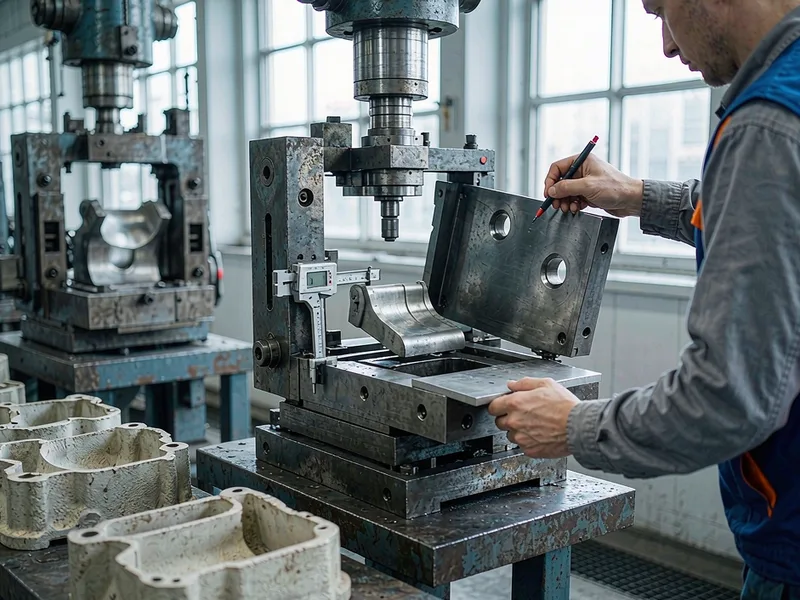
These are the numbers we hold on production tooling. Treat them as the design baseline, not the absolute floor. Every value assumes a smooth, as-cast surface with no added texture.
| Feature | Minimum draft | Standard draft | Notes |
|---|---|---|---|
| Outside wall, shallow (under 25 mm deep) | 1.0° | 1.5° | Easiest surfaces to fill and release |
| Outside wall, deep (25–100 mm) | 1.5° | 2.0° | Adds metal usage on tall parts |
| Inside wall / core, shallow | 1.5° | 2.0° | Shrinkage pulls metal onto the core |
| Inside wall / core, deep | 2.0° | 3.0° | Check ejector capacity on tall cores |
| Cored hole, 5–25 mm diameter | 1.5° | 2.0° | Thin cores also need cooling |
| Ribs and bosses | 1.0° | 1.5° | Full height, both faces |
| Slides and lifters | 2.0° | 3.0° | Travel adds to the release demand |
| Textured or textured-look surface | 2.5° | 3.5° | Texture depth of 0.05 mm adds roughly 1° |
Values in degrees, measured on the surface normal to the parting plane. Add draft locally, not everywhere, when a feature carries risk.
Why Inside Walls Need More Draft Than Outside Walls
Think about what the metal does as it cools. The casting shrinks toward its own center. On an outside wall, the steel is outside and the metal pulls away from it — the gap opens up, so release gets easier. On an inside wall, the core sits inside the part, and the shrinking metal closes onto it. The core now grips the casting with real force.
That asymmetry is why inside draft runs 1 to 1.5 degrees higher than outside draft on the same part. Many designers mirror one value across the whole drawing. Then the tool shop adds the extra draft on cores anyway, and the CAD model no longer matches the delivered casting. Set cores and bosses to a higher value from the start.
Deep cores make it worse. A tall core has more contact area, so total grip scales with height. It also heats up further from the cooling line, so it expands more. Keep the draft generous and plan core cooling at the design review, not after the tool is cut.
Texture, Shrinkage, and Other Draft Multipliers
Surface texture changes the surface area your part slides against. A rough finish acts like coarse sandpaper on the die, and the release force climbs fast. Add one degree for every 0.025 to 0.05 mm of texture depth. A blasted or leather-grain finish that sits 0.1 mm deep wants roughly 2 extra degrees beyond the smooth baseline.
Shrinkage already covers the drag in the drawing numbers. But alloy choice shifts the rate. A380 and ADC12 sit near the common 0.5 to 0.7 percent range. The squeeze over a long core can push a marginal draft into a sticking problem on the first shot of a cold die.
Slide travel matters too. A slide that moves 40 mm before the part clears needs more taper than one that moves 10 mm. The die casting draft angle must clear the full travel distance, not just the feature depth. When in doubt, add a degree on anything that moves.
Finally, match draft to ejector design. If the part has a small ejector area and heavy draft, pins will still mark or dimple it. Generous draft lowers the force needed, and lower force means fewer ejector pin witness marks on visible surfaces.
How to Set Draft Without Killing the Design
Draft steals metal and can shift a feature past a tolerance. Start with the thinnest wall and the tallest feature. Those two numbers drive how much metal the draft adds, and how much the top of a tall wall moves off nominal. On a 100 mm wall, one degree moves the top edge about 1.7 mm. Two degrees moves it 3.5 mm. Check that shift against your fit and your weight before you accept it.
Where you cannot afford the metal, cut the height instead. A shorter core needs less draft to release. Splitting a deep core into two shallower steps often beats fighting a 100 mm pull with tight draft. On some parts, a slide that forms the feature sideways removes the deep pull entirely.
Areas that get machined afterward can carry less draft, because the machine removes the surface the die gripped. But never design zero draft and assume a later operation saves the cast. The casting must still release from the die, and it releases before any machining starts.
Bring your draft questions to the DFM review. We check every pull direction, add a draft callout to the model, and flag the features that will fight the die. A minute in CAD beats a week at the press. Send us your drawing for a die casting draft angle review with your alloy and target volume, and you will get marked-up values you can release to a tool shop.

External Links
- North American Die Casting Association (NADCA) — the source for the industry product design guides that set draft angle and wall thickness practice.
- ASME Y14.5 — defines the dimensioning and tolerancing rules you need when you call out draft on a drawing.
- ASTM B85 — standard specification for aluminum-alloy die castings, covering chemistry and mechanical properties by alloy.
FAQ
What draft angle should I use for die casting?
Start at 1.5 degrees on outside walls and 2 degrees on inside walls and cores. Go to 3 degrees on deep cores, slides, and textured surfaces. Thin features and short pulls can run closer to 1 degree if the tool is well cooled.
Why does inside draft need to be larger than outside draft?
Because the casting shrinks onto the core as it cools. On an outside wall the metal pulls away from the steel, which helps release. On a core the metal grips harder. That difference is worth about 1 to 1.5 degrees.
Can I use zero draft on a die casting?
No. Even 0.5 degrees fights the die, and straight walls seize almost every time. If a feature needs a truly vertical surface, plan to machine it after casting instead of casting it square.
How does surface texture change the die casting draft angle?
Texture adds drag. Add roughly 1 degree for every 0.025 to 0.05 mm of texture depth. A deep leather grain can need 2 extra degrees over a smooth as-cast surface.
Does a smaller draft angle cost more money?
Often yes. Tight draft raises release force, which speeds up die wear, scuffing, and scrap. Those costs land in your unit price. Adding a degree in CAD is free and usually cheaper than repairing the tool later.