Minimum Wall Thickness in Aluminum Die Casting: Design Rules
Minimum wall thickness in aluminum die casting decides whether your part ships on time or turns into a scrap bin statistic. Wall thickness drives fill, solidification, porosity, cycle time, and cost — all at once. This guide gives you the working numbers we use on real projects, the reasons behind them, and the traps that catch even experienced designers.
Key Takeaways
- Practical floor for aluminum die casting walls: 0.8–1.0 mm on small parts, 1.5–2.5 mm on large ones.
- Going below the floor raises porosity, cold shuts, and scrap rates sharply.
- Uniform walls beat thin walls. A constant 2 mm section outperforms a mix of 1 mm and 4 mm.
- Thicker is not stronger in castings — bulk sections add shrink voids, not strength.
- Use ribs, not slabs, when you need stiffness.
Why Wall Thickness Governs Everything
In high pressure die casting, the minimum wall thickness you choose decides how metal fills the cavity in 20 to 80 milliseconds. Heat leaves the alloy through the steel die walls, and it leaves fastest where the casting is thinnest. A section that is too thin freezes before it fills. The result is a cold shut: two metal fronts meet, fail to fuse, and leave a seam you can crack with a thumbnail.
Too thick is just as bad. A heavy section keeps feeding long after the thin walls around it have locked. Shrinkage porosity collects in the last spot to solidify. That internal void sits exactly where you do not want it — under a machining boss, beside a threaded insert, or across a pressure boundary.
Thickness sets cycle time too. A 2 mm wall solidifies in a few seconds. A 6 mm wall can take three to five times longer. Since the die cannot open until the casting is solid, thickness multiplies directly into piece price. We tell every customer the same thing: you pay for seconds on every shot.
Finally, wall thickness controls distortion. Uneven sections cool at different rates, so the thin part of the casting locks while the thick part still shrinks. That residual stress warps the part after ejection. Flatness callouts fail, and the part needs straightening or scrap. Uniform walls avoid most of this before it starts.
Working Numbers by Alloy and Part Size
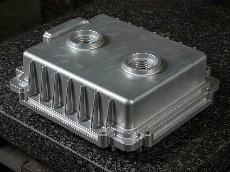
The table below reflects what a well-run HPDC cell can produce at volume. Treat it as a starting point, not a limit — good die design can push these down, but every step below the norm adds cost.
| Part characteristic | Alloy | Typical minimum wall | Practical floor |
|---|---|---|---|
| Small, under 25 cm² projected area | A380 / ADC12 | 1.0–1.5 mm | 0.8 mm |
| Medium, 25–100 cm² | A380 / ADC12 | 1.5–2.5 mm | 1.0 mm |
| Large, 100–500 cm² | A380 / ADC12 | 2.5–3.5 mm | 1.5 mm |
| Very large or structural | A360 / AlSi10Mg | 3.0–4.5 mm | 2.0 mm |
| Thin-wall electronics housing | ADC12 | 0.8–1.2 mm | 0.6 mm* |
*0.6 mm is achievable only with vacuum assist, tight thermal control, and short flow paths. It is not a starting spec for a new program.
Design Rules That Keep Walls Workable
Rule one: keep sections uniform. If you must change thickness, taper it. A step from 3 mm to 1.5 mm over one radius builds a shrink defect at the corner. A gradual taper over 2 to 3 wall thicknesses lets metal feed continuously into the thin zone.
Rule two: use ribs for stiffness. Ribs let you hold a low minimum wall thickness without giving up stiffness. A rib at 60 to 70 percent of the adjacent wall thickness adds bending stiffness at a fraction of the solidification cost. Ribs also break up large flat areas that would otherwise warp or show sink marks opposite the rib.
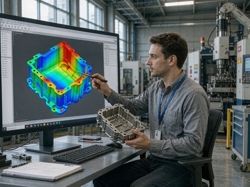
Rule three: watch bosses and holes. A boss for a fastener is the thickest feature on most castings. Core it out. Leave 2 to 2.5 mm of wall around the cored hole and the boss solidifies with the rest of the part instead of feeding a void into the base. The same logic applies to any machining pad — the casting only needs stock, not bulk.
Rule four: check flow length. Metal loses heat as it travels. A 0.8 mm wall can fill 50 mm from the gate; it cannot fill 300 mm. When a design forces thin walls across a long flow path, add gates or thicken the far end. This is a conversation to have at DFM, not after the first shot.
Rule five: round every corner. Sharp inside corners concentrate stress and block metal flow. A fillet radius of at least 1 mm — ideally one third of wall thickness — costs nothing at the die and removes two defect modes at once.
Cost Impact You Can Quantify
Minimum wall thickness shows up on your quote in three ways. First, cycle time: a thinner part means more shots per hour, and that alone can move piece price 15 to 30 percent. Second, metal weight: alloy is bought by the kilogram, and heavy sections waste material you never see once the part is machined. Third, scrap: a design near the thin limit runs higher scrap, and that cost lands in your unit price whether or not the supplier shows it as a line item.
The trade-off goes the other way too. Cutting walls below what the process needs to save a few grams usually backfires. Porosity goes up, leak-test failures go up, and the supplier adds inspection cost. We have seen programs where a 0.2 mm over-thin spec cost more in leak rejects than it saved in metal.
The right move is to set the minimum wall thickness that fills reliably at your part’s flow length, keep everything else uniform, and stop there. That wall is usually thicker than the record books say and cheaper than any alternative.
How We Review Wall Thickness on New Projects
Every drawing we receive goes through the same screen. We check the thinnest section against flow length and alloy. We check the thickest section for cored-out potential. We run fill simulation on anything with walls under 1.5 mm or aspect ratios past 4:1. Then we return a DFM sheet with red, yellow, and green marks so you can see exactly which features carry risk.
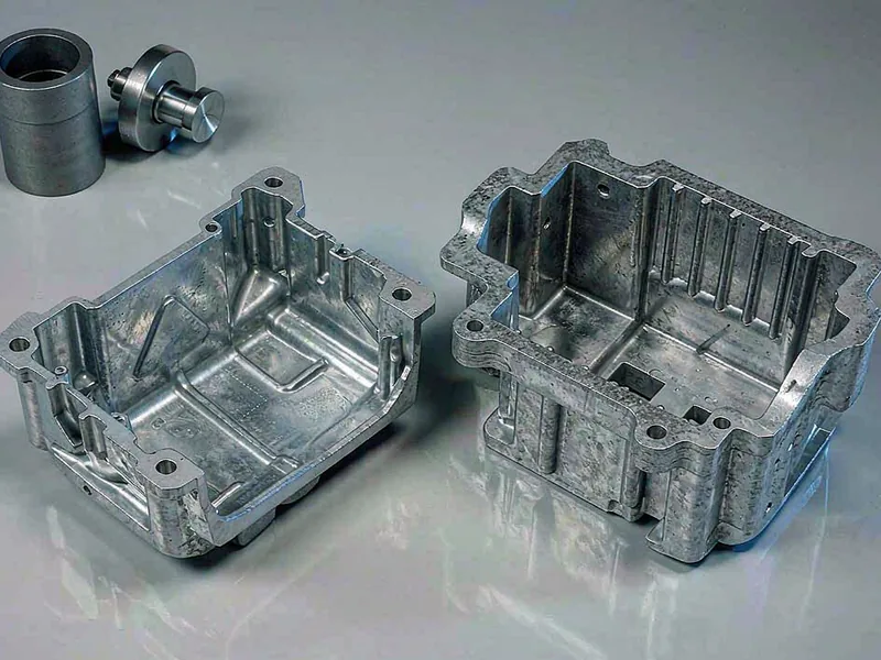
Most issues resolve in one revision cycle. The changes that matter most are usually free: a fillet added here, a boss cored out there, a thickness taper smoothed. Fixing these before tooling starts costs hours. Finding them after first article costs weeks.
If you are designing a new aluminum die casting and want a second opinion on wall thickness, send us the drawing. We will mark it up and return it with the working numbers for your alloy, your size, and your annual volume.
External Links
- North American Die Casting Association (NADCA) — industry standards, including the widely referenced product design guides covering wall thickness and draft.
- International Organization for Standardization (ISO) — source of ISO 8062 castings tolerance system referenced across global supply chains.
- ASTM B85 — standard specification for aluminum-alloy die castings, covering alloy chemistry and mechanical properties.
FAQ
What is the thinnest wall for aluminum die casting?
On small parts with short flow paths, 0.8 mm is a realistic production floor. On larger parts, plan for 1.5 mm or more. Anything below these numbers needs vacuum assist and very tight process control.
Does a thicker wall make the casting stronger?
No. Bulk sections add shrinkage porosity, which lowers fatigue and pressure performance. Stiffness comes from ribs and geometry, not mass. A ribbed 2.5 mm wall outperforms a solid 6 mm slab in almost every real load case.
How does wall thickness affect porosity?
Thick sections cool last and collect the shrink voids. Every place the wall exceeds roughly 4 mm in aluminum is a candidate for porosity. Core, rib, or taper these zones instead of leaving them solid.
Can wall thickness vary across one part?
Yes, but transition gradually. Use a taper over 2 to 3 wall thicknesses, never a sharp step. Keep the ratio between the thickest and thinnest sections under about 3:1 where possible.
Does thin wall save money?
It cuts cycle time and metal weight, which lowers price — until scrap rises. Past the process limit, every tenth of a millimeter you remove adds rejects. The cheapest wall is the thinnest one that fills reliably, not the thinnest one on paper.