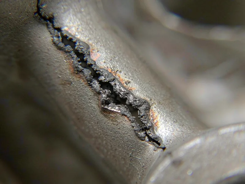
Hot tearing die casting is a solidification crack, not a service crack. It opens while the part is still partly liquid, at a hot spot where shrinkage strain outruns the strength of the semi-solid metal. The tear has a ragged, oxidized face and usually starts at a thick-to-thin junction, a sharp internal corner or a boss base. It is prevented by design and by thermal control, and it is rarely repairable on a structural part.
Key Takeaways
- Hot tears form between the coherency point and the solidus, roughly 540-580 °C for Al-Si die casting alloys.
- They start where a hot spot meets a restrained section, not where the part looks thinnest.
- A 1.5 mm fillet at a boss base often removes the tear; a thicker boss in the same place usually makes it worse.
- Ejection temperature, die thermal balance and ejector pin layout decide whether a marginal design tears or survives.
- Any tear on a pressure boundary or a fatigue section is a reject; welding is not an accepted repair there.
- Corrective evidence is a hot-spot map from solidification simulation plus a die temperature log, not a promise to be careful.
What Hot Tearing Is and Where It Starts
A casting does not shrink evenly. As the last liquid pockets solidify, the solid network is already load-bearing, and further contraction has to be absorbed as strain. If the network is still fed by liquid, it heals. If it is isolated, the grain boundaries are held together by a thin liquid film with almost no strength, and the strain concentrates there. The film tears, and the tear is preserved as a ragged crack with oxidized faces.
That sequence explains the location. A hot tear needs a region that stays liquid longer than its neighbors, and a region that restrains contraction. A thick boss on a thin wall supplies the first, because the boss holds heat. The surrounding thin wall, already frozen, supplies the second. The tear opens at the boundary between them, which is why it often runs around a boss base rather than across a wall.
The temperature window
For ADC12 and A380, the coherent shell starts to carry load near 580 °C, and the last liquid disappears near 515 °C. The vulnerable window is just above the solidus, where the fraction of solid is high enough to transmit strain and low enough that grain boundaries are still wet. A die that ejects at 300 °C has already passed that window inside the die; a die that ejects at 200 °C has passed it under restraint, which is usually better for tear resistance and worse for dimensional stability.
Why the tear face looks the way it does
A hot tear has a rough, dendritic, dull gray-to-dark face with visible oxide color, because the metal was exposed to air while still hot and partly liquid. A cold crack is bright, straight and transgranular, and it happens below about 200 °C when the alloy is brittle. Reading the fracture face is the fastest way to assign the cause, and it costs one photograph at 20x.
Hot Tear, Cold Crack, Quench Crack or Heat Check
Six crack types reach a die caster’s quality desk, and only one of them, the hot tearing die casting crack, is a solidification defect. The others belong to ejection, heat treatment or the die itself, and each has a different corrective action and a different cost owner. A buyer who cannot tell them apart will accept the wrong explanation and pay for the same failure twice.
| Type | When it forms | Fracture face | Usual location | Primary cause |
|---|---|---|---|---|
| Hot tear | During solidification, 540-580 °C | Rough, dendritic, oxidized, dull | Boss base, thick-to-thin junction, sharp internal corner | Shrinkage strain on a starved hot spot |
| Cold crack | At ejection, below 200 °C | Bright, straight, transgranular | Thin wall near an ejector pin, sharp edge | Ejection force, die lock, insufficient draft |
| Quench crack | During water quench after solution treatment | Bright, brittle, often branching | Internal corners, sudden section change | Thermal gradient too steep for the section |
| Heat check | On the die, after thousands of shots | Fine crazing network on steel | Die cavity surface, gate area | Thermal fatigue of H13 |
| Trimming crack | At the trim press | Sheared edge with a bright lip | Along the parting line, near gates | Trim die clearance or part support |
| Machining tear | During milling or drilling | Smears, torn metal, no oxidation | Machined faces, tapped holes | Tool geometry, feed rate, coolant |
The color test is decisive in most cases. A crack that has seen high temperature in air carries an oxide tint. A crack that opened at room temperature is bright, because no oxidation had time to form. Hold the part under a bench light, look into the crack with a 10x loupe, and photograph it before anyone cleans it. Cleaning removes the evidence that assigns the cost.
Heat check is a die failure, not a part failure. Crazing prints fine raised lines that read as cracks to a buyer who has not seen them, and they stay cosmetic unless the die has eroded enough to move dimensions. The fix is die maintenance, covered in the guide to heat checking as a die failure mode.
Design Rules That Remove the Hot Spot
Hot tearing die casting defects are cheaper to design out than to process out. The die casting process gives five geometry handles, and all of them work by the same principle: give the shrinking section something to pull against, or remove the isolated hot spot entirely.
Rule 1: taper wall transitions
A change from 4 mm to 2 mm over a 2 mm step creates a hot spot and a stress concentration. A taper of 1:3 or gentler spreads the thermal gradient, so the last liquid is fed from the thick side while the thin side is already strong. On a housing with a 5 mm pad on a 2.5 mm wall, the taper is the difference between a tear rate near zero and one that follows the pad outline.
Rule 2: radius every internal corner
An internal corner with a 0.5 mm radius concentrates stress and heat. A radius of at least half the local wall thickness, and 1.5-3 mm at a boss base, moves the hot spot into a region that can be fed. Sharp corners also start quench cracks after T6, so the change buys protection twice.
Rule 3: keep bosses thinner than the wall they sit on
A solid boss is a heat reservoir. A boss wall of 0.5-0.7 times the nominal wall, with a cored hole, holds less heat and feeds better than a solid pillar. Where a solid boss is unavoidable, a gusset or a local squeeze pin gives the shrinking section a feed path.
Rule 4: do not stack ribs into a cross
Four ribs meeting at one point create a hot spot no die cooling can reach. Offsetting the ribs, or reducing rib thickness to 0.6-0.8 of the wall, breaks the thermal mass. The same applies to ejector bosses and to mounting pads that sit close together.
Rule 5: simulate before cutting steel
Solidification simulation shows the last-to-freeze nodes and the contraction strain at each junction, which is exactly what a hot tear prediction needs. A hot-spot map produced before the die is cut costs a fraction of a die correction after the first trial, and it gives the buyer a document to review rather than an opinion to trust.
Process Control: Ejection, Thermal Balance and Restraint
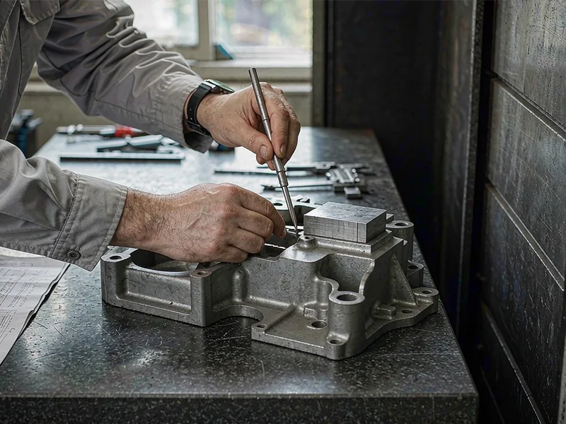
Once the geometry is fixed, the remaining variables are thermal and mechanical, and they are all adjustable on the machine. A die that tears at one set of parameters and runs clean at another is telling you the design is marginal, which is worth knowing before the program scales. A hot tearing die casting problem that responds to a temperature change is a thermal balance issue in most cases.
Ejection temperature
Ejecting too hot tears parts, because the section is still weak and the ejector pins push on a shell that has not developed strength. Ejecting too cold cracks them, because the alloy is brittle and the shrinkage stress is fully developed. For ADC12 housings, an ejection temperature of 250-320 °C at the thick section is a working range, measured with a contact probe on the part. A part that tears at 340 °C and runs clean at 290 °C has a cooling problem, not a design problem.
Die thermal balance
A hot spot is often a cooling problem in disguise. If the boss side of the die runs 40 °C hotter than the wall side, the boss stays liquid longer and the tear follows. Partitioned die temperature control, baffles in the boss insert, and a separate circuit for the gate area bring the differential under about 30 °C. The article on die thermal balance covers the circuit layout that makes this repeatable.
Ejection force balance
Ejector pins that are uneven in height, or concentrated on one side, bend the part as it leaves the die. That bending adds strain to a section that may still be weak, and a hot tear can result even when the thermal profile is correct. Pin height within 0.05 mm, and pin area sized for the local wall, are basic checks often skipped on a new tool.
Intensification and squeeze
Intensification pressure of 500-1,200 bar feeds the section while it is still connected to the biscuit. A local squeeze pin on a known hot spot adds pressure exactly where feeding is short, and it is the standard remedy for a thick section that cannot be redesigned. The trade is a pin mark, which must sit outside cosmetic zones.
How HKX Prevents Hot Tears Before Steel Is Cut
At HKX, prevention of hot tearing die casting defects begins in the DFM review, before a die block is ordered. The engineering team runs a solidification simulation on the customer’s 3D model and marks every node that freezes after the surrounding wall by more than a set interval. Those nodes are the candidate hot spots, and each one gets a decision: add a radius, taper the transition, core the boss, add a squeeze pin, or move a cooling circuit into the insert. The review also checks rib junctions and ejector boss locations, because those are the two features that most often defeat an otherwise good thermal layout. On the die, cooling is partitioned so that boss inserts, the gate block and thin walls run on separate circuits with their own flow meters. Temperature is checked on the cavity surface at start-up and every two hours, and a differential above 30 °C between adjacent zones is a process deviation.
Ejection temperature is measured on the part at the robot gripper, and ejector pin heights are verified with a dial indicator at each die assembly. For parts that will be T6 treated, HKX reviews the quench path as well, because an aggressive water quench will crack an internal corner that survived solidification.
The output is a short process sheet: hot-spot map, cooling circuit layout, ejection temperature window, pin heights and any squeeze pin settings. When a customer later reports a crack, that sheet shows whether the part was produced inside the qualified window, and the conversation moves to a measured fact instead of a theory about the die.
Accept, Repair or Reject: A Crack Disposition Table
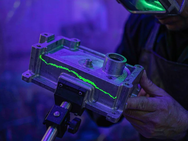
A crack is not one commercial event. A hairline tear on a hidden rib of an industrial bracket and the same tear on a gearbox housing that holds oil are different decisions, and the difference should be written into the drawing before the first shipment. Hot tearing die casting defects that reach a buyer usually arrive with a supplier opinion attached; the table below replaces that opinion with a rule.
| Finding | Part function | Disposition | Evidence required |
|---|---|---|---|
| Hairline tear under 0.5 mm, not through wall | Non-structural, non-sealing | Accept with deviation | Penetrant test report, sectioned photo at 50x, tear depth measurement |
| Tear under 1 mm, through-wall not confirmed | Industrial housing, no pressure | Conditional accept after re-test | X-ray per ASTM E505, pressure decay if sealing, simulation hot-spot map |
| Any through-wall tear | Any | Reject | Containment record, 8D, revised die or process plan |
| Tear at a pressure boundary | Pump, valve, motor cover | Reject; no welding | Leak test data, X-ray, corrective action with die change |
| Tear in a fatigue-loaded section | Structural bracket, suspension part | Reject; no welding | X-ray, section macro, design review with FEA input |
| Crack found after machining | Any | Reject lot pending review | Pre-machining inspection data, machining stock record, die repair plan |
Repair welding is the most negotiated item in this table, so it needs a written policy. Welding is acceptable on a non-structural, non-sealing casting with customer approval, after the crack has been ground out to sound metal and the repair has been inspected by penetrant test. It is not acceptable on a pressure boundary, on a fatigue section, or on a part that will be anodized, because the weld and the heat-affected zone respond differently to the anodizing bath and show as a color patch. Cap the number of repairs per part, typically one, and record the location on the inspection report.
The evidence package should include three items beyond the visual report: a penetrant test to ASTM E165, a radiograph to ASTM E505 where the section allows it, and the solidification hot-spot map for the tool. Those three separate a tear that can be tolerated from a tear that will grow, and they tell the buyer whether the fix is a radius change or a cooling change. According to the North American Die Casting Association, casting defects should be classified by their effect on function rather than by appearance alone, which is the principle behind the table.
Frequently Asked Questions
Can a hot tear be repaired by welding?
On a non-structural, non-sealing casting, sometimes, with customer approval, after grinding out the crack and passing a penetrant test. On a pressure boundary or a fatigue section, no. The weld brings porosity and a hardness mismatch, and the repair usually costs more than scrapping the part and fixing the die.
Why does the tear appear only on some shots?
Because the process runs near a limit. A small change in die temperature, spray coverage, cycle time or alloy chemistry moves local solidification time enough to cross the threshold. That variability is the signal that the design has no margin, and the fix is a geometry or cooling change.
Is a hot tear the same as a shrinkage crack?
They are related but not identical. A shrinkage crack is a hot tear driven by feeding shortage in a thick section, and the terms are often used interchangeably on the floor. The practical difference is location: a shrinkage crack sits in the middle of a heavy section, while a hot tearing die casting defect usually follows a thick-to-thin junction.
Does a bigger fillet always help?
Up to a point. A radius of half the wall thickness or more removes the stress concentration, but a very large fillet adds mass at the junction and can create a new hot spot. The useful range at a boss base is 1.5-3 mm on typical housings, confirmed by simulation rather than by habit.
Can T6 heat treatment cause cracks in a die casting?
Yes, though that is a quench crack rather than a hot tear. A water quench pulls the surface into tension faster than a thin internal corner can accommodate. Polymer quench or a slower transfer reduces the risk, and pre-existing porosity or a small radius makes it worse.
What should a supplier submit after a tear investigation?
The hot-spot map from simulation, the die temperature log for the affected run, the ejection temperature record, the penetrant or X-ray report, and a named change with a date. A response that lists only “adjusted parameters” is not evidence, because it cannot be verified on the next lot.
Author: HKX Engineering Team
HKX — Ningbo Hexin Mould Co., Ltd., an aluminum die casting manufacturer in Ningbo, China, with 30+ years of tooling experience, in-house machining and finishing, ISO 9001 and IATF 16949 certification, and customers in more than 20 countries.
Talk to the HKX Engineering Team
Send a drawing and a photo of the crack, and HKX will say which crack type the fracture face indicates, where the hot spot sits in the current design, and what a radius, taper or cooling change would cost in die work. For a new part, HKX runs the solidification simulation before quotation and returns the hot-spot map with the DFM report, so a hot tearing die casting risk is visible before the die is cut. Production lots ship with the first article report, penetrant and X-ray records, die temperature logs and the process sheet. Parts such as industrial gear reducer housings run on 160-2,500 t cold chamber machines with in-house machining. To start the review, contact our engineering team with the drawing, the annual volume and the test standard.