Die Casting Simulation: What Mold Flow Analysis Predicts Before Steel Is Cut
Die casting simulation lets you see a shot before anyone cuts steel. The software fills a virtual cavity with virtual metal, cools it, and shows where trouble will land. You get fill patterns, air traps, cold shuts, shrinkage porosity, and hot spots. All of it arrives weeks before the first trial shot. That timing is the whole value. A change in the model costs an afternoon. The same change in hardened H13 costs a new insert, a new timeline, and a new invoice. This guide covers what a fill and solidification model really shows, which outputs you should trust, and how we use it on real programs at hkxcast.com.
Key Takeaways
- Die casting simulation predicts fill, solidification, air entrapment, and porosity before tooling exists.
- It saves money by moving fixes from the die shop to the CAD model.
- Results are only as good as the inputs: alloy data, gate area, thermal layout, and machine settings.
- Not every output is equally reliable. Fill and hot spots are strong. Exact porosity percentages are not.
- Simulation supports DFM decisions. It never replaces trial shots or process tuning.
What the Solver Actually Calculates
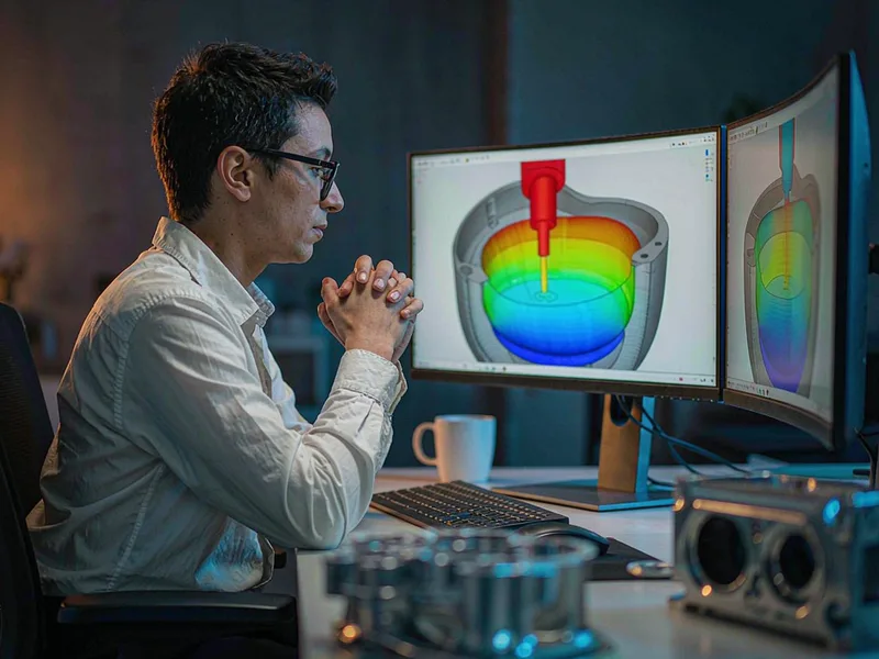
At its core, a simulation run solves two coupled problems: fluid flow and heat transfer. The solver divides the cavity into millions of small cells, then tracks metal velocity, pressure, and temperature in each one across time steps measured in milliseconds.
Filling is the first pass. The software injects metal through the runner at your chosen gate velocity and records where the front travels. Fast fill means less heat loss. Slow fill risks a cold shut. The model shows both in one run.
Solidification comes second. Once the cavity is full, the solver tracks how heat leaves through the die steel. It marks the last regions to freeze, since those collect shrink porosity. It also flags hot spots in the die itself, which drive soldering and thermal fatigue.
Air is the third piece. Every cavity traps gas. Good venting pushes it out. Bad venting seals it into the casting as blowholes or surface blisters. A filling simulation shows the air path and the last-filled pockets, which is where you place vents.
Finally, the solver handles the machine. Shot profile, intensification pressure, die temperature, and spray pattern all feed in. Change the intensification pressure and the porosity map shifts. That sensitivity is useful, and it is the reason we run several cases per part.
Predictions You Can Trust, and Predictions You Cannot
A die casting simulation run returns dozens of plots. They do not all carry equal weight. Treating every output as equally trustworthy leads to bad decisions. The table below reflects how we rank them in daily practice.
| Prediction | Typical accuracy | How to use it | Reliability |
|---|---|---|---|
| Fill pattern and fill time | Within 5–10% | Set gate position, runner balance, vent location | High |
| Air entrapment zones | Location good, size rough | Place overflows and vents | High |
| Hot spots in the die | Location reliable | Plan cooling lines and spray | High |
| Cold shut risk | Ranking reliable | Compare design variants | Medium |
| Shrinkage porosity | Trend only, not % | Compare variants, not absolute values | Medium |
| Absolute tensile strength | Not predicted | Validate with test bars | Not usable |
| Exact scrap rate | Not predicted | Confirm with trial shots | Not usable |
The lesson is simple. Use simulation to rank options and locate risk. Do not use it to promise a porosity number in a purchase order. Anyone who quotes an exact internal void percentage from a model alone is overselling the method.
Inputs Decide the Answer
A solver is a calculator. Wrong numbers in, wrong numbers out. The most common failure we see is a model built on default material data with no thermal calibration at all.
Alloy properties matter. A380 and ADC12 share a family, but their latent heat and thermal conductivity differ. Use the correct database entry for your melt, not a generic aluminum preset.
Boundary conditions matter more. Die temperature, cooling channel flow rate, spray time, and contact resistance between metal and steel all shift the result. We log real die temperatures from production and feed them back into the next model. That single step improves accuracy more than any mesh refinement.
Gate area and shot profile matter most of all. The gate is where you control velocity, and velocity controls fill. Get the gate size wrong in the model and every downstream prediction drifts with it.
Mesh quality sets the ceiling. A coarse mesh runs fast and lies about thin walls. We refine around gates, ribs, and cored holes where gradients are steep, and leave bulk regions coarser to keep run times sane.
Benefits of Simulation
The payoff from a study shows up in three areas: cost, quality, and time.
On cost, a die casting simulation pays for itself fast. Every issue found in the model is an issue you do not pay for in steel. A gate moved in CAD costs nothing. A gate moved after hardening costs a weld, a re-heat-treat, and a week of downtime. We have seen a single gate relocation in simulation remove a die repair that would have run into five figures.
Quality: simulated programs start closer to a stable process. First-shot parts arrive with fewer cold shuts and less porosity, so the path from trial to production shortens. Leak test yields on sealed housings improve too, because the porosity map told us where to add squeeze pins before the die was bored.
Time: the biggest gain is not technical, it is calendar. Design review happens in a week instead of after a failed trial. You get answers to questions like “what happens if we move this boss 8 mm” in hours, not in tooling cycles.
How We Run Studies on New Programs
Our workflow is fixed, because a repeatable process beats a clever one-off.
Step one: DFM screen. We check wall thickness, draft, parting line, and ejector placement first. There is no point simulating a geometry that cannot eject.
Step two: runner and gate design. We size the gate from the required fill time and projected area, then balance the runner so all cavities finish together.
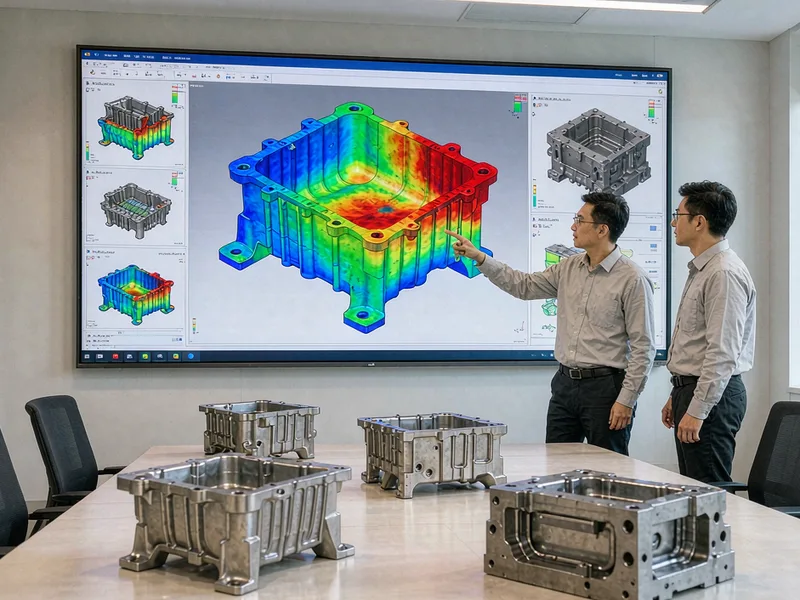
Step three: baseline run. One model, realistic inputs, full shot. We read fill pattern, air traps, and hot spots before touching anything.
Step four: variant runs. We test alternatives — a wider gate, a relocated overflow, an added cooling line. Each variant runs against the same baseline so the comparison holds.
Step five: report and freeze. We issue a short report with screenshots, risk marks, and the chosen design. That document travels with the die for the rest of its life.
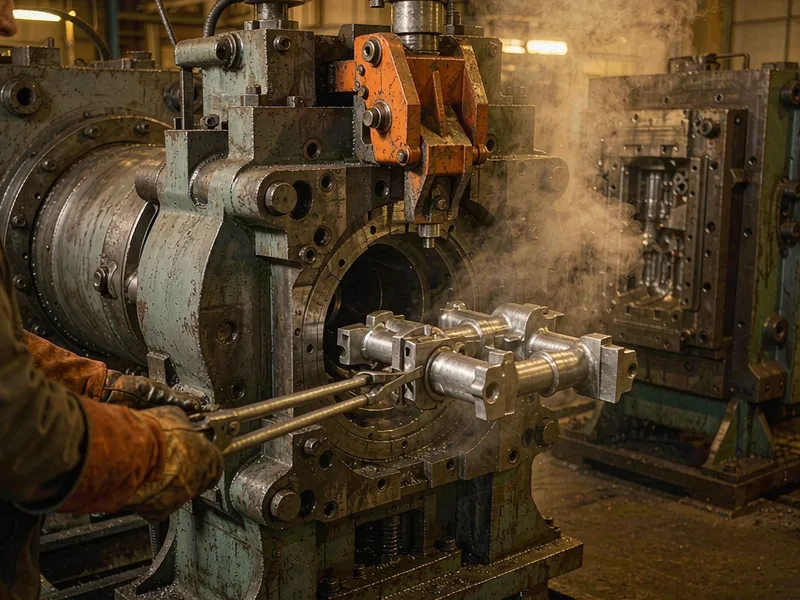
During trials we compare measured data against the model. Mismatches usually trace back to a boundary condition, not the solver. Every comparison makes the next program sharper.
A simulation study is a design tool, not a crystal ball. Used with real inputs and honest expectations, it removes most of the guesswork from tooling. Used carelessly, it just produces colorful pictures. If you want a fill study and DFM report on your next part, send us the 3D model and we will show you what the metal will do.
External Links
- North American Die Casting Association (NADCA) — publishes design guides and process data that anchor simulation inputs for HPDC work.
- ASM International — reference source for aluminum alloy thermophysical properties used in fill and solidification models.
- ASTM B85 — standard specification for aluminum-alloy die castings, useful when linking model alloy data to a real chemistry.
FAQ
What does die casting simulation predict?
It predicts fill pattern, fill time, air entrapment, cold shut risk, hot spots in the die, and shrinkage porosity trends. It does not predict exact tensile strength or a precise scrap rate. Use it to compare designs and locate risk.
Does die casting simulation replace trial shots?
No. It reduces the number of trials and shortens the path to a stable process. You still need a real die, real metal, and a real machine to confirm the result and set production parameters.
How accurate are these fill models for HPDC?
Fill pattern and hot spot locations are usually reliable. Porosity prediction is directional rather than absolute. Accuracy depends on inputs, especially die temperature, gate area, and contact resistance. Calibrated models track reality well.
When should we run a mold flow study?
As early as possible. Run a baseline study as soon as casting geometry is stable, and variant studies before the die design freezes. Changes cost hours in CAD and weeks in hardened steel.
Can a filling simulation handle thin-wall parts?
Yes, but it needs a finer mesh. Thin walls fill in milliseconds and show steep temperature gradients. Coarse meshes smear those gradients and understate cold shut risk. Refine the thin sections before trusting the result.