Overflow & Venting Design in Die Casting Dies
Air is the enemy in high pressure die casting. The plunger drives metal into the cavity in milliseconds, and whatever gas sits in front of that metal has to go somewhere. If it cannot escape, it ends up as porosity, blisters, or a short fill. Good die casting venting design gives that gas a path out, and paired overflows give the cold metal and trapped air a place to land. Get both wrong and you will chase blisters, black marks, and leak failures for the life of the die. This guide covers the overflow design and venting rules we apply on production tools, plus the checks we run before cutting steel.
Key Takeaways
- Vents should sit at the last points to fill, sized so gas escapes but metal does not.
- Typical vent depth for aluminum die casting runs 0.05 to 0.15 mm, with wider lands behind them.
- Overflows catch cold metal and oxide, so the main cavity fills clean.
- Vent area should grow as it leaves the cavity — the exit must be wider than the entry.
- Vacuum assist buys you more vent area and lower porosity when a part needs it.
Why Venting Decides Casting Quality
A die cavity is not empty when the shot starts. It holds air, plus gas from the release agent and the plunger lubricant. That gas compresses, heats, and burns where it gets trapped. The result is a black oxide patch and a hard carbon deposit on the die steel.
Poor die casting venting design also creates back pressure. Trapped gas pushes back on the incoming metal front, slowing and chilling it. A front that stalls becomes a cold shut or a short fill. Gas that never escapes becomes blowholes under the skin, and those show up only after machining.
Venting is a two-way street. You want the gas out, but not the metal. Metal that enters a vent flashes off as a thin fin, which sticks in the slot and blocks it. So vent depth is a compromise, and overflows take the cold metal first.
Vent Sizing and Placement
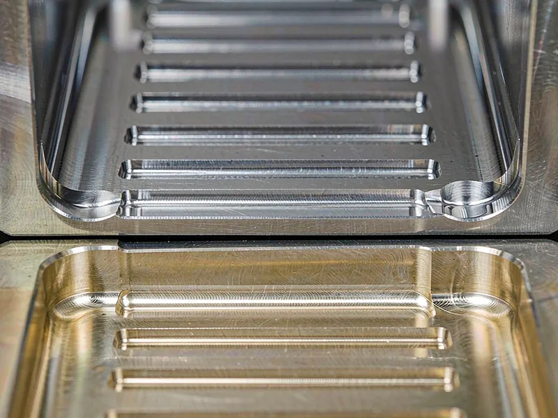
Vent depth is the number that matters most. Too shallow and gas cannot move fast enough during a 40 ms fill. Too deep and the metal flashes through and welds itself into the slot. The table below shows the ranges we hold on aluminum tools. Die casting venting design has to live inside them.
| Feature | Typical size | Purpose | Watch out for |
|---|---|---|---|
| Vent depth at the cavity edge | 0.05–0.08 mm | Lets gas out, blocks metal | Flash if opened too far |
| Vent depth at the exit | 0.10–0.15 mm | Speeds gas flow near the end | Blockage from flash and soot |
| Vent land length | 15–25 mm | Adds resistance against metal flow | Too long, gas cannot clear |
| Vent width | 6–12 mm per slot | Spreads gas over a usable area | Too wide weakens the die edge |
| Vent area vs. gate area | 0.5–1.0× | Balances flow into and out of the cavity | Undersized vents choke the fill |
| Overflow volume | 15–30% of casting | Traps cold metal and oxide | Too small, defeats the purpose |
| Overflow thickness | 0.8–1.5 × wall | Freezes last, holds the cold front | Too thin, freezes before the shot ends |
Values are working ranges for common aluminum HPDC alloys. Exact sizes depend on cavity volume, fill time, and whether the die runs vacuum assist.
Placement follows the fill pattern. Vents belong at the last points to fill, where the metal front arrives. A vent at a location that fills early only lets clean metal flash out. Simulation shows those last points before you cut the steel.
Vents also release gas from the release agent as it hits hot metal. That is why a die can run clean for weeks, then make black marks after a spray change. Give every low spot and deep rib a path to a vent.
Overflow Design That Actually Works
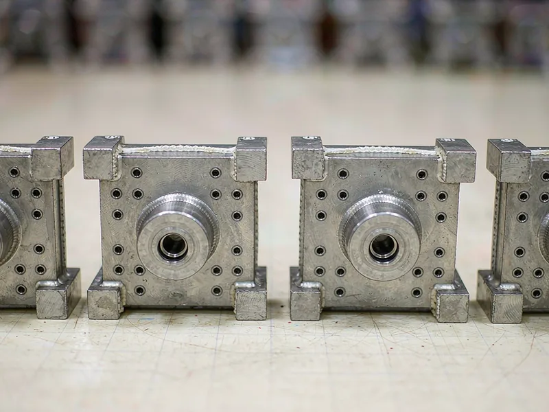
Overflows are small pockets cut at the cavity edge and fed by a thin gate. Metal reaches them last, so the coldest metal and loosest oxide flow in first. By the time metal arrives, it has lost heat and picked up oxide, and you want neither in the part.
Size overflow by flow length and wall thickness. A short, thick part needs small overflows. A long, thin part needs generous ones, because the front has travelled far and cooled a lot. Start near 15 to 30 percent of casting volume, then adjust after simulation.
Overflow thickness is often set too thin. If the pocket is thinner than the wall, it freezes before the shot finishes and never fills. The metal backs up into the cavity and the air has nowhere to go. Keep it at or slightly above wall thickness.
Overflows also need a small vent. Once the pocket fills, remaining gas must keep moving. A vented overflow doubles as an air exit and lets the pocket fill completely.
Vacuum Assist and Advanced Venting
Some parts cannot be cast clean without added help. Structural castings, thin housings, and anything leak-tight push venting past what a simple slot can do. Three upgrades help.
Vacuum assist pulls gas out of the cavity through a manifold and a valve before the shot. The cavity starts below atmospheric pressure, so gas escapes easily and the metal front travels faster and stays hotter. Vents can be larger, so porosity drops. It costs more at the die and adds a control step, but it pays back on leak-tight parts.
Laminated vents stack thin steel plates into a slot. The gaps form a vent channel of controlled depth, and the rough structure breaks up any flash. They resist clogging better than a plain slot.
Thermal vents use a small water line behind the vent. Cooling the steel near the exit freezes metal faster and stops it advancing into the slot. Use it where a thin section forces high metal velocity at the vent.
Track the same rule across all three. Die casting venting design should grow the gas path as it leaves the cavity and add resistance to the metal path at the same time.
Maintenance Rules That Keep Vents Working
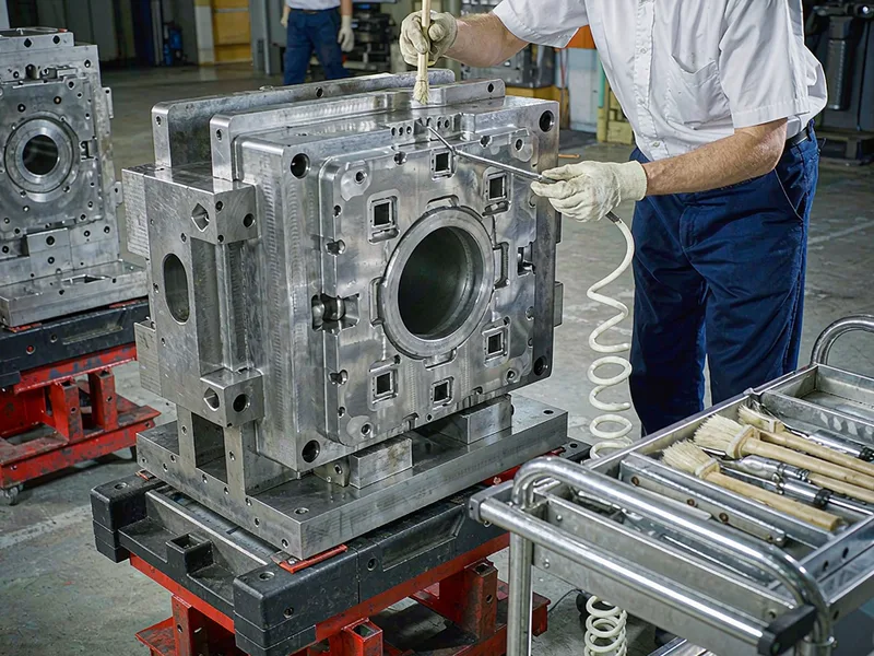
A vent is only as good as its maintenance. Flash builds up in the slot, soot from burned lubricant fills the gaps, and the effective vent area shrinks within a few thousand shots. Porosity then climbs, and operators blame the process instead of the tool.
Clean vents on a fixed schedule. Check the vent land after every run, and re-cut the vent depth when it drifts past the drawing. When flash appears where there was none before, check the vent first.
Wash the vent area on every die change. Release agent left in the slot turns to carbon, and carbon blocks gas. A short cleaning cycle during long runs saves scrap.
Keep the process window closed around your overflow design. If the shot profile changes and metal reaches the vent faster, flash starts. If cooling changes and the front arrives colder, the overflow stops filling. Both look like venting faults but come from the process.
Send us your part model and fill requirements. We will return a vent and overflow layout with the last-fill points marked, sizes for your alloy, and a cleaning schedule that matches your volume.
External Links
- North American Die Casting Association (NADCA) — industry reference for die design covering venting, overflows, and the process limits behind them.
- ASM International — technical source on aluminum alloy solidification and gas behavior in die casting.
- ASTM B85 — standard specification for aluminum-alloy die castings, including acceptance of internal soundness.
FAQ
What is die casting venting design?
It is the layout of vents, overflows, and vacuum channels that let trapped gas and cold metal escape a die cavity. It sets vent depth, vent area, and overflow size, so it decides how much porosity ends up in the part.
How deep should a vent be in an aluminum die casting die?
Start at 0.05 to 0.08 mm at the cavity edge and open to 0.10 to 0.15 mm at the exit. Keep the land 15 to 25 mm long. Deeper vents flash and clog; shallower vents choke the gas flow.
Why does my casting show black marks and blisters?
Trapped gas is burning or expanding under the skin. Open the vents, add an overflow at the last point to fill, or check that the slots are not blocked with carbon and flash.
How large should an overflow be on a die casting die?
Plan for overflow volume around 15 to 30 percent of the casting volume, with a thickness at or above the wall. Size it up for long flow paths, then confirm in fill simulation.
When do I need vacuum assist in a die casting die?
When the part is thin-walled, structural, or must pass a pressure test, and normal venting cannot hit the porosity target. Vacuum lowers cavity pressure and lets you run larger vents.