Parting Line Design: Where to Split a Die Casting Mold
The die casting parting line design is the single decision that shapes everything else on your tool. It sets where the two die halves meet, where flash forms, which features sit in the cover half, and which need slides. Move the line 10 mm and you may delete two slides, cut tool cost, and clean up a cosmetic surface. Pick it badly and you fight flash, porosity, and tolerance stack-ups for the life of the program. This guide walks you through how we choose a parting line on real aluminum die casting programs. You will get the placement rules, the cost drivers, and the exceptions that break the rules. Use it before you freeze your design.
Key Takeaways
- The parting line is the plane where the fixed and moving die halves separate.
- Place it in one flat plane whenever you can — every step or jog adds cost.
- Keep the line off visible and sealing faces to avoid flash and sealing problems.
- Features that sit across the line need slides, which raise tool cost and cycle time.
- Draft, flash, and tolerances all follow from the line you choose.
What the Parting Line Decides
Every die casting tool is two steel blocks that clamp together and fill with liquid metal. The surface where those blocks meet is the die casting parting line design outcome — the boundary between the cover half and the ejector half. Every feature sits on one side of that boundary or the other. Nothing can span it without help.
That single boundary decides a lot. It sets where flashing appears, because a small gap at the shutoff always lets a thin fin of metal escape. It sets which surfaces can hold tight tolerances, since dimensions across the line stack two die halves and their closing accuracy. It also decides how many slides, lifters, and core pulls the tool needs.
Most importantly, the parting line sets tool cost. A flat line machined into two blocks is the cheapest option. Every step, jog, or pilot adds machining, fitting, and hand work. Those hours show up directly in your tooling invoice.
Placement Rules We Apply on Every Job
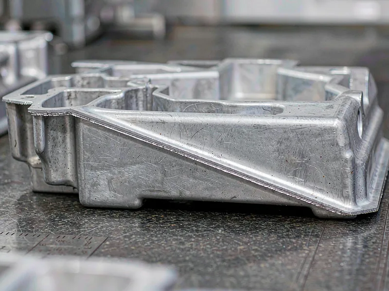
Start with the simplest line that releases the part. Then check it against these rules, in order. Each rule you break adds cost somewhere in the program.
| Design consideration | Best practice | Cost if ignored |
|---|---|---|
| Overall shape | Single flat plane | Extra machining and hand fitting |
| Line position | Along the largest cross-section | Undercuts, locked part, slides needed |
| Visible surfaces | Keep line off show faces | Flash visible, extra deburring labor |
| Sealing faces | Machine separately after casting | Leak paths at the flash line |
| Deep ribs and bosses | Keep in one die half | Side actions and higher tool cost |
| Tolerances across the line | Loosen by 0.1 mm or more | Parts out of spec, high reject rate |
| Ejector placement | Line so ejectors hit stiff sections | Dents, bent parts, longer cycle |
Rules are ranked. A flat line that keeps show faces clean beats a clever line that saves metal but adds a slide.
Flat Line, Stepped Line, or Curved Line
A flat line is the goal. It lets the tool shop machine both halves in one setup, and it keeps the closing force even across the whole face. Most housings, brackets, and covers can use a flat line if the designer is willing to accept a slightly deeper draw on one side.
Stepped lines appear when a part has features at very different heights. Two or three steps are normal on complex parts. Each step adds a shutoff face that must fit tightly, and each one adds a place for flash to form. Keep steps to a minimum and put them where the geometry already changes.
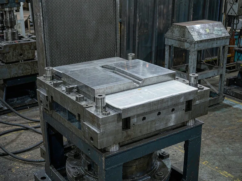
Curved lines follow a radius to hide flash or to balance flow. They work well on round parts and on castings with a domed top. The catch is that a curved shutoff is harder to fit and harder to maintain. The edge wears, flash grows, and the tool shop has to rework the face. Use a curved line only when it solves a real problem.
The step-versus-curve choice often comes down to one thing: how visible will the flash be? On a hidden internal surface, take the flat line. You can always add a small step later to change where flash lands.
How the Line Drives Cost and Cycle Time
Tool cost moves faster than most designers expect. A flat line on a moderate housing might need 2 to 4 slides for side holes. Jog the line and you can add 2 more, plus a lifter. Each slide adds hundreds of hours of design and build time, plus maintenance and wear parts.
Cycle time follows. Every slide has to open and close on each shot. A tool with six side actions can run several seconds slower than the same part with two. At high volume, that difference is real money on every hundred thousand parts.
Flash also costs. A line that crosses a sealing groove will leak until someone machines it. A line that lands on a visible face needs extra deburring labor on every part. Those are recurring costs, not one-time tool costs.
Tolerances tighten the argument. Dimensions on one side of the line hold well. Dimensions that cross it stack the closed position of both halves. Give cross-line dimensions at least 0.1 mm more room and expect the tool shop to flag anything tighter at DFM review.
Where the Line Beats the Textbook
Sometimes the cleanest line is not the obvious one. If a cast boss must sit exactly opposite a machined pad, put both in the same die half. That removes a stack-up and protects the tolerance. You accept a slightly more complex line elsewhere.
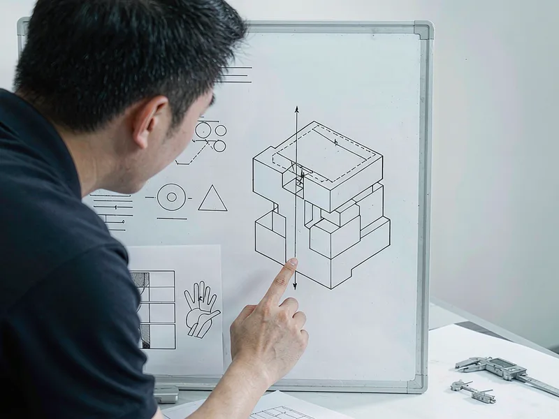
Undercuts are the other case. A part with a side hole or an external groove cannot release from a simple two-part tool. The fix is a slide, a lifter, or a redesign. Always check whether you can move the feature to a surface that the main pull already covers. That change is usually free, and it removes the side action entirely.
Volume settles hard calls. At low volume, a simple tool with more hand work often wins. At high volume, spending on slides pays back quickly through cleaner parts and shorter cycle. Bring your annual volume to the design review so we can weigh both sides.
If you are designing a new part, send us the model before you commit to a line. We mark the pull direction, propose the split, and list the slides it avoids. Fixing the die casting parting line design in CAD costs an afternoon. Fixing it after the tool is cut costs weeks and real tooling money.
External Links
- North American Die Casting Association (NADCA) — publishes the design guides that cover parting line selection, draft, and tooling practice.
- ASM International — reference source on die materials, heat treatment, and the wear behavior that drives slide maintenance.
- International Organization for Standardization (ISO) — home of the ISO 8062 castings tolerance system used for dimensions across a die.
FAQ
What is a parting line in die casting?
It is the boundary where the two die halves meet and separate. Metal can flash at that seam, and dimensions that cross it stack the closing accuracy of both halves. It sets flash location, tolerance behavior, and how many slides the tool needs.
Where should I place the die casting parting line design?
Put it in one flat plane along the largest cross-section, away from visible and sealing faces, and keep deep ribs in a single half. Then check that the part releases with the main pull and no undercuts.
Does a stepped parting line cost more?
Yes. Every step or jog adds a shutoff face to machine and fit, and often adds a slide or lifter. A flat line machined in one setup is the cheapest option and the easiest to maintain over the life of the tool.
How close can tolerances be across the parting line?
Tighter than most designers assume, but not free. Give cross-line dimensions at least 0.1 mm more than single-half dimensions, and let the tool shop confirm anything tighter at the DFM review.
Can the parting line run through a visible surface?
It can, but you will see flash there. Deburring removes it, and that labor repeats on every part. Keep the line on a hidden or machined face when appearance matters.