A CMM inspection casting layout is a full dimensional record of one part, measured on a coordinate measuring machine and reported feature by feature against the drawing. Reading it takes four checks in order: confirm the drawing revision and datum scheme, confirm the environment and probe record, read the deviation column rather than the actual, then look for the few characteristics that sit outside their limit. Everything else on the page supports those four checks.
Key Takeaways
- A layout measures every dimension on the drawing; a first article adds material and performance evidence on top of that.
- The datum statement in the header must match the drawing. A layout built to a different datum scheme is not comparable, however clean the numbers look.
- Aluminum expands about 23 µm per meter per °C, so a 300 mm casting measured 5 °C off reference shifts roughly 35 µm.
- Position tolerance on a hole earns bonus tolerance as the hole departs from maximum material condition, so read the allowance column, not just the callout.
- One out-of-tolerance feature on a 90-characteristic layout is information. Twelve scattered failures usually mean a datum or fixturing problem, not a bad part.
- Ask for the raw measurement file and the ballooned drawing. A PDF summary alone cannot be re-checked by your own quality team.
What a CMM Layout Actually Contains
A layout is not a pass or fail certificate. It is a table of measurements, and the value is in the detail around the table. Three blocks carry that detail: the header, the alignment record and the results grid.
Everything below applies to any CMM inspection report you receive, whether the part is a 40 g bracket or a 12 kg housing. The report format is standard across labs; what changes is how much of it you actually verify before you sign.
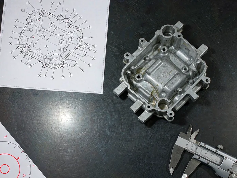
The header identifies the part, the drawing revision, the program version, the machine and the probe configuration. The alignment record states which features established the datum reference frame and how much error the alignment itself carried. The results grid lists every characteristic with nominal, limits, measured value, deviation and verdict.
Reading the header before the numbers
Buyers skip the header and go straight to the red cells. That is backwards. If the layout was run to drawing revision C and your engineering change is at revision D, the numbers describe a part you no longer build. If the program version is older than the last tool correction, the results describe a die that no longer exists.
Check the environmental record next. A credible report states ambient temperature at the start and end of the run, part soak time, and the machine’s calibration status. Reference temperature for dimensional metrology is 20 °C, as defined in ISO length standards, and a shop that measures at 28 °C without compensation is reporting a different part than the one on the drawing.
The columns that matter
| Column | What it means | How to read it |
|---|---|---|
| Characteristic ID | Balloon number matching the marked-up drawing | Must match your drawing balloons one to one, or the report cannot be audited |
| Nominal | Design value from the drawing | Compare against your current revision, not an older PDF |
| Tolerance | Bilateral, unilateral or geometric callout | Watch for one-sided tolerances printed as symmetric |
| Measured | The value the machine returned | Read to one more decimal than the tolerance, not fewer |
| Deviation | Measured minus nominal, signed | Signed drift across a family of features shows a datum or thermal bias |
| Allowance | Total permitted deviation including bonus | On MMC callouts this is larger than the printed tolerance |
| Verdict | Pass or fail flag | Check the flag against the numbers; flag logic errors are common |
A mid-size aluminum housing typically carries 60-120 characteristics. A CMM inspection that reports 12 of them and calls itself complete is a partial inspection, and should be labelled that way.
Reading the Datum Reference Frame
Most disputes about CMM inspection casting data trace back to one line in the header: the datum statement. A datum reference frame is the coordinate system the part was aligned to, and every deviation on the page is expressed relative to it. Change the frame and the same physical part produces different numbers.

The 3-2-1 rule
A primary datum plane constrains three degrees of freedom, a secondary plane two, and a tertiary plane or bore one. That is the classic 3-2-1 sequence, and the drawing callout A|B|C tells the programmer the order. Measuring the same part with B and C reversed is a different measurement, not a rounding difference.
The geometry is defined in ASME Y14.5, and the practical consequence for a casting is large. A die cast housing might use the machined mounting face as datum A, two dowel holes as B, and one edge as C. The as-cast skin is never a datum, because it moves with die wear and draft.
Datum targets versus full features
Large or unstable castings are often specified with datum targets, small pads or areas that contact the fixture instead of an entire face. Targets make the measurement repeatable, because a 200 mm as-cast face is never perfectly flat and a three-point contact on that face is arbitrary.
If your drawing shows targets and the report shows a best-fit plane over the whole face, the two are not equivalent. Best-fit alignment minimizes total error across all points, which flatters the part. Target-based alignment reports the error where the part actually touches its mating surface.
Datum shift on MMB callouts
When a datum feature is called out at maximum material boundary, the part is allowed to shift within the clearance that exists at that boundary. A layout that reports position without accounting for permitted shift will fail parts that assembly accepts. Ask the programmer to state whether shift was applied and how much was consumed.
Fixture and clamp distortion
Thin-walled housings move when clamped. A 2 mm wall section pulled 0.05 mm by a clamp reads as a flatness failure that disappears when the part is released. Good layouts state the clamp locations and, for thin parts, report both clamped and free-state values for the critical faces.
Position Tolerance, Bonus Tolerance and the Math
Position is the characteristic buyers misread most often, and it is also the one that decides whether a casting passes a functional gauge. The reported deviation for a hole is not the distance from nominal center. It is twice the radial distance, because the tolerance zone is a diameter.
The true position formula
For a hole measured at offsets dx and dy from nominal, true position equals 2 × √(dx² + dy²). A hole sitting 0.09 mm off in X and 0.12 mm off in Y reports 0.30 mm. Compare that against the allowance, not against the radius.
Bonus tolerance at MMC
A callout of Ø0.20 at MMC on a Ø10.00 ±0.10 bore allows extra position error as the bore grows. Maximum material condition for a hole is its smallest permitted size, 9.90 mm. A bore measured at 10.08 mm has departed 0.18 mm from MMC, and that departure is added to the tolerance zone.
| Characteristic | Callout | Measured | Allowance | Verdict | Reading |
|---|---|---|---|---|---|
| Bore 1 position | Ø0.20 M to A B C | TP 0.30 at Ø10.08 | 0.38 with bonus | Pass | Fails if bonus is ignored; this is the most common false rejection |
| Bore 2 position | Ø0.20 M to A B C | TP 0.10 at Ø10.02 | 0.32 with bonus | Pass | Well centered; size is near nominal |
| Datum A flatness | 0.05 | 0.06 | 0.05, no bonus | Fail | Form tolerances earn no bonus; the mounting face will rock |
| Boss perpendicularity | 0.10 to A | 0.04 | 0.10 | Pass | Margin is healthy; no action needed |
| Bore 3 diameter | Ø10.00 ±0.10 | 10.11 | 9.90-10.10 | Fail | 0.01 mm over; check whether the bore is pre-machined |
| Wall thickness | 3.0 ±0.3 | 2.62 | 2.70-3.30 | Fail | Thin wall plus position failure on the same side points to die shift |
Two lessons sit in that table. First, four of six rows can only be judged with the allowance column present, so insist that the report carries it. Second, one diameter over size by 0.01 mm and one wall thin by 0.08 mm on the same side is a pattern: the die half shifted, and the fix is in the tool, not in the part.
When the tolerance is bilateral but the process is not
Castings do not fail symmetrically. A bore drifts one way with die wear, and a wall drifts one way with thermal balance. A layout that keeps failing the same limit in the same direction is telling you the process mean has moved, and a capability study will show it before scrap rate does.

Which Numbers to Read First
A 90-characteristic report takes about ten minutes to read properly, and the order matters more than the speed. A CMM inspection run can be flawless and still tell you nothing useful if you start with the wrong column. Start with the characteristics that carry function, then work outward.
Start with the interface features
Mounting faces, bearing bores, dowel holes and sealing grooves decide whether the part assembles and seals. Everything else is secondary. If those four groups are inside tolerance with margin, the part will work even if a cosmetic rib is 0.2 mm off.
Read them as a group, not individually. Bearing bore position, bore diameter and face flatness interact: a bore that is centered but tilted will still bind a shaft. A layout reports perpendicularity and position separately, and the buyer has to combine them.
Then read the pattern, not the count
Three failures on one side of the part suggest a datum or clamp issue. Three failures scattered across unrelated features suggest either a real process problem or a measurement problem. Twelve failures across every characteristic usually means the alignment was wrong, and the correct action is to re-measure rather than to scrap.
Compare deviations, not verdicts. If every X coordinate reads +0.04 mm, the part is not randomly out; the datum origin moved. A single feature at +0.15 mm with everything else near zero is a local die issue, such as a broken insert or a shifted slide.
Capability, not just conformance
A layout proves one part. Capability proves the process. For special characteristics, a PPAP submission typically needs an initial process study with a Ppk of 1.67 or better across at least 25 subgroups of five consecutive parts. A layout showing every value at mid-tolerance tells you nothing about the next 10,000 parts.
When a supplier reports a capability index, check the sample size and the subgroup structure. A Cpk of 2.0 from ten parts is arithmetic, not evidence.
Rounding and resolution
A tolerance of ±0.05 mm reported to two decimals cannot distinguish a pass from a marginal fail. The general rule is to report one more decimal than the tolerance resolution, and to record the machine’s own repeatability so the reader knows the noise floor.
How HKX Builds and Reads a Layout
At HKX, the CMM inspection casting report is produced on a temperature-controlled granite in the Ningbo quality lab, and the program is written from the customer drawing rather than from the model alone. That distinction matters, because a model dimension and a drawing callout can disagree, and the drawing governs acceptance.
The sequence starts with ballooning. Every characteristic on the drawing receives a number, and the same number is used in the CMM program, the report and the inspection plan. A housing with 94 characteristics produces a 94-row report, and no row is dropped because it is difficult to reach.
Alignment comes next. The team establishes the datum reference frame exactly as called out, records the alignment residuals, and holds the part at 20 ± 2 °C for at least four hours before the run. Aluminum moves 23 µm per meter per degree, so a 300 mm cover measured straight off a warm line would be reported 30-35 µm away from its cold-state geometry.
Probe selection follows the smallest feature. A Ø2 mm stylus reaches the M4 threaded inserts and the 3 mm slots, and the program records the tip number and calibration date so a later run can be traced to the same configuration. Scanning is used for the mounting face and the sealing groove; discrete points are used for bores, where a scan can bias the diameter.
Reporting is where HKX spends the most effort. Each report states the drawing revision, program version, machine ID, probe ID, ambient temperature at start and end, soak time, fixture ID and operator. Deviations are signed, allowance is shown for every MMC callout, and out-of-tolerance rows carry a short comment naming the likely cause. Reports ship as PDF plus the native measurement file, and the ballooned drawing goes with them so the customer’s quality team can audit the mapping. For a new program the first three parts are measured, and the spread between them is reviewed before the report is released.
Comparing CMM Results With Other Inspection Methods
A CMM is not the only way to check a casting, and for some characteristics it is the wrong tool. Knowing which method produced a number tells you how much weight to put on it, and knowing what a CMM inspection was set up to answer tells you whether the report addresses your question at all.
| Method | Best for | Typical uncertainty | Limit you should know |
|---|---|---|---|
| Bridge CMM, discrete points | Bores, positions, GD&T | 2-5 µm | Slow per feature; fixturing affects thin walls |
| Scanning CMM | Freeform surfaces, flatness, profiles | 5-10 µm | Point density can bias a diameter high |
| Structured light scan | Full-field comparison to CAD, first article | 20-50 µm on 300 mm | Shiny as-cast skin needs spray; not a substitute for a bore check |
| Height gauge and pin gauges | Shop-floor trends, quick checks | 10-20 µm | No datum control; good for monitoring, not for acceptance |
| Functional gauge | Go and no-go on assembly features | Set by gauge design | Proves fit, says nothing about margin |
| X-ray, ASTM E505 | Internal porosity, not dimensions | Not dimensional | Complementary; a clean X-ray does not prove a bore position |
The practical split is straightforward. Use a CMM for anything the drawing controls with GD&T, use a scanner when you need to know where a whole surface sits rather than whether one point passes, and use gauges for daily monitoring. A supplier who sends a scanner screenshot in place of a dimensional report has not answered the question.
What to request in the purchase order
Write the inspection requirement as a deliverable, not an intention. Name the report type, the number of pieces, the characteristics covered, the environment record and the file format. State that the datum scheme must follow the drawing, and that MMC bonus must be shown.
State the acceptance rules for borderline results too. Whether a characteristic measured at exactly the limit passes, and how many dimensions may sit in the warning band, belongs in the document rather than in a later argument. The reporting conventions behind those rules trace back to the ASME Y14.5 dimensioning and tolerancing standard, and NADCA’s product standards cover the casting-side defaults that drawings often leave implied.
For ongoing production, add a layout frequency and a capability requirement per special characteristic. Ask for the measurement file, not only the PDF. If the part feeds an assembly line, ask for the gauge strategy too, so that your receiving inspection and the supplier’s layout agree on what a conforming part is. The relationship between drawing tolerance and tool tolerance is covered in mold tolerance vs part tolerance, and the tryout evidence that precedes a first layout is described in T1 samples and tryout reports.
Two related pages help set expectations before the first report arrives: the automotive die casting quality process, and the aluminum motor end covers range, where bore position and face flatness are the governing characteristics.
Frequently Asked Questions
How is a CMM layout different from a first article inspection?
A layout is the dimensional portion: every characteristic measured on one part. A first article adds material certification, performance tests, process parameters and tooling records. In practice a PPAP dimensional results submission is a layout with the supporting documents attached, and buyers should ask for the layout even when the full package is not required.
How many parts should a layout cover?
Three to five parts from the same run is the common practice for a dimensional CMM inspection, enough to see whether a characteristic is centered or drifting. Capability studies are separate and need far more: at least 25 subgroups of five consecutive parts for a Ppk of 1.67 or better.
Why do two labs report different numbers for the same part?
Usually three reasons: a different datum scheme, a different temperature at the time of measurement, or a different probe and alignment strategy. Aluminum moves about 23 µm per meter per °C, so a 6 °C difference on a 300 mm part accounts for roughly 40 µm before anything else is considered.
What does the M next to a tolerance mean?
M means maximum material condition. On a hole, it allows extra position tolerance as the hole grows beyond its smallest permitted size, because a larger hole has more clearance to assemble. The extra amount is the bonus, and a CMM inspection casting report should show it in a separate allowance column.
Should I reject a part with one out-of-tolerance characteristic?
Not automatically. Check whether the characteristic is functional, whether it is a form tolerance with no bonus, and whether the deviation is inside measurement uncertainty. A 0.005 mm failure on a 0.05 mm tolerance is inside the noise of many setups. A 0.06 mm flatness on a 0.05 mm datum face is a real defect.
Can a supplier self-approve a layout?
A supplier can generate the CMM inspection data, but acceptance belongs to the customer. Ask for the native measurement file and the ballooned drawing, re-check a sample of characteristics in-house, and record the program version. Independent verification on two or three features is enough to expose a mapping error across the whole report.
Author: HKX Engineering Team
HKX — Ningbo Hexin Mould Co., Ltd., an aluminum die casting manufacturer in Ningbo, China, with 30+ years of tooling experience, in-house machining and finishing, ISO 9001 and IATF 16949 certification, and customers in more than 20 countries.
Talk to the HKX Engineering Team
Send a drawing with the GD&T scheme and the inspection standard your receiving team uses, and HKX will confirm which characteristics the CMM program will report and which need a functional gauge. The deliverable is a ballooned drawing, a full dimensional layout with the environment and probe record, the native measurement file, and a short list of the characteristics most likely to drift once the die passes 50,000 shots. Buyers who review a layout before approving a die correction spend less on tool rework later. To start that review, contact our engineering team and include the critical characteristics and the quantity of parts per layout.