A first article inspection casting report proves that the first parts off a new die, cast and fully machined, meet every drawing requirement rather than just the nominal dimensions. It lists each characteristic taken from the drawing, the gauge and method used, the measured value, the stated tolerance and a pass or fail disposition. On a cast-plus-machined part the report has to separate as-cast features from machined features, because the two sit in different tolerance systems, use different datums and fail in different ways.
Key Takeaways
- A first article inspection casting report is a dimensional and material proof of the process, not a sample approval slip.
- Cast features run to ISO 8062 CT grades; machined features run to the drawing tolerance block and GD&T, so the report needs both logics.
- Inspect three to five parts from consecutive shots and name the cavity each one came from.
- Establish the machining datum from a machined face and two bores, never from an as-cast surface that will be cut away.
- Capability, not only conformance, separates a useful FAI from a stack of numbers that pass by luck.
- Review the report before the die is hardened and before the fixture is released for production, when change is still cheap.
Why Cast and Machined Parts Need Two Inspection Logics
A casting is a process part. Its dimensions are set by die temperature, shot profile, die draft, shrinkage and ejection, so a cast dimension is a distribution, not a value. A machined feature is a machine part. Its dimensions are set by the fixture, the tool and the program, so the spread is narrow and the tolerance is usually much tighter. One inspection report has to hold both, and buyers who treat them as one system usually end up arguing about the wrong number.
The cast side is governed by ISO 8062-3, which assigns casting tolerance grades from CT1 to CT16 by size range and process. A 60 mm aluminum die casting typically lands in CT5 to CT7, which is roughly a plus or minus 0.15 to 0.30 mm band depending on the grade, the dimension type and whether the feature crosses a parting line. That is ten times looser than a machined bore. When a drawing shows an untoleranced cast dimension next to a machined bore with a 0.02 mm limit, the two numbers are not comparable, and the report must label them as different characteristic classes.
The machined side is governed by the drawing itself, normally under ASME Y14.5 dimensioning and tolerancing rules. Position, profile, flatness and perpendicularity are evaluated against a datum reference frame, and the frame only exists after the part is machined. This is the point that catches suppliers with weak metrology: they measure a machined bore from an as-cast boss, get a number, and never realize the datum was never established.
There is a third logic that sits between the two, and it is the one that decides whether the part can be made at all. Machining stock is the material left on a cast surface for the cutter to remove. If the FAI shows a machined face cleaning up with 0.1 mm of stock on one part and 0.9 mm on the next, the casting is not stable, even though both parts pass. A first article inspection casting report that records stock depth on every machined face turns that hidden variable into a visible one.
Building the Inspection Plan Before the First Part Is Cut
The inspection plan is written from the drawing, not from the first part. Start by ballooning every characteristic: each dimension, each GD&T callout, each note that can be measured, each material or surface requirement. A typical machined housing such as an aluminum motor end cover carries 80 to 200 ballooned characteristics. Then classify each one as critical, major or minor, because the sample size, the gauge and the acceptance rule all follow the class.
Critical characteristics are the ones that stop the part working or stop it passing a legal or safety requirement: a bearing bore position, a sealing face flatness, a thread depth in a pressure cavity, an alloy chemistry limit. These get 100 percent inspection on the FAI parts and a documented gauge study. Major characteristics affect fit or function but not safety, such as mounting hole positions and overall height. Minor characteristics are cosmetic or non-functional, such as a fillet radius or an untoleranced draft.
Sample size deserves a written rule. Three parts minimum, five for a multi-cavity die, taken from consecutive shots in the same production run, with the cavity number recorded for each. One part from one cavity proves the die can make a part. Five parts across cavities proves the die can make the part repeatedly, which is the only claim a production approval should rest on.
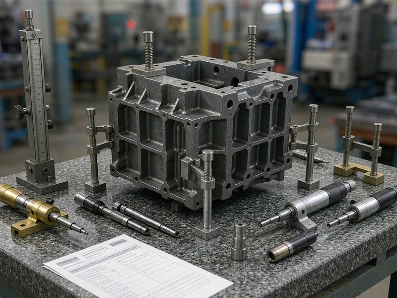
Two more decisions belong in the plan. The first is the datum strategy: which machined surfaces establish the frame, in which order, with what clamping force. The second is gauge selection, because a 0.05 mm tolerance cannot be signed off with a caliper. Bore gauges, air gauges, a CMM with a stated uncertainty, thread gauges and functional Go/No-Go fixtures each cover a different band, and the report should name the instrument and its calibration status for every critical row.
Matching the Measurement Method to the Feature
Method errors are the most common reason an FAI report is rejected at the customer’s end. The measurement was taken, the number was in tolerance, and the method could not have detected the condition the drawing actually controls. The table below is the pairing used on cast and machined aluminum parts, and it is a reasonable basis for a purchase order annex.
| Feature | Method | Typical tolerance band | FAI sample | Failure it misses if done badly |
|---|---|---|---|---|
| Machined bearing bore diameter | Bore gauge or CMM, two diameters at three depths | IT7 to IT8, 0.02-0.05 mm | 100% of FAI parts | Barrel or taper hidden by a single two-point reading |
| Bore position to datum | CMM with established datum frame | 0.05-0.15 mm position | All parts | Datum shift when the frame is built on an as-cast face |
| Sealing face flatness | CMM scan or surface plate with indicator | 0.05-0.10 mm | All parts | Local depression in the middle of the face |
| As-cast wall thickness | Ultrasonic thickness gauge or sectioned part | CT6, plus or minus 0.2-0.3 mm | 3 sections per part | Thin wall on the far side of the cavity |
| Cast boss position | CMM, cast datum scheme | CT6 to CT7 | All parts | Draft-related drift at the boss tip |
| Machining stock on cast face | CMM before and after machining, or blue check | 0.3-0.8 mm nominal | All parts, all faces | Insufficient stock on one cavity |
| Internal soundness | Radiography per ASTM E505 | Level 2 critical, Level 3 general | 3 parts per cavity | Shrinkage under a machined sealing face |
| Leak tightness | Pressure decay or air-under-water | 0.5-1.5 bar, 30-60 s | 100% of FAI parts | Leak path through interconnected porosity |
| Alloy chemistry | Optical emission spectrometry | ADC12 or A380 per ASTM B85 | One sample per heat | Silicon or copper drift from recycled charge |
Read the fourth and sixth rows together, because they carry the most risk on a cast part. Wall thickness controls solidification and strength, and machining stock controls whether the part cleans up at all. Both are cheap to check at FAI and expensive to discover at the machining center, where a shallow cut leaves a black skin on the sealing face and the whole lot becomes rework.
The last row matters more than buyers expect. Chemistry drives shrinkage, fluidity and machinability, so a heat that sits outside the silicon window changes the dimensional spread on every downstream feature. A first article inspection casting package without a chemistry certificate is incomplete regardless of how good the CMM numbers look. The lab report belongs on page one, not in an appendix.
How HKX Runs a FAI on Cast and Machined Parts
At HKX, the FAI sequence starts at the furnace rather than at the CMM. A direct-reading spectrometer confirms the melt before the first shot, so the silicon, copper and iron windows for ADC12 or A380 are on record before any dimensional work begins. That sample is filed with the heat number, which links the report to the ingot lot and to the castings poured from it. The same discipline behind OES alloy verification at the furnace carries through to every certificate issued with a layout.
The layout itself uses five parts from consecutive shots, with the cavity number stamped on each. HKX builds the machining datum frame on the finished mounting face and two machined bores, then repeats the frame check at the end of the run to catch fixture drift.
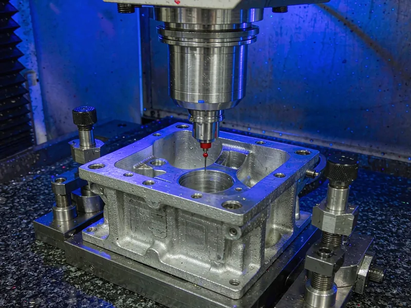
Sealing faces get a full scan for flatness rather than a few spot readings. Every machined face also carries a stock-depth reading taken before and after cutting, which is how the plant detects a die that is drifting before the customer sees a scrap part.
Internal quality is checked by radiography at the critical zones marked on the drawing, with acceptance written to ASTM E505 levels, and pressure-tight parts run a decay test at the specified pressure and hold time. Draft angles, parting-line mismatch and ejector-pin witness marks are recorded as separate rows, because those are the cast features that generate the most cosmetic disputes later. The finished package includes the ballooned drawing, the measurement sheet, the material certificate, the radiographs and a signed layout report. HKX issues that package in PPAP Level 3 format when the program is automotive, and in a simplified layout format for industrial buyers who only need traceability.
What Belongs in the FAI Clause of the Purchase Order
Most quality disputes over first articles are not technical. They come from a purchase order that said “FAI required” and never defined what that means. Five lines of contract language remove almost all of the ambiguity, and they cost nothing to write.
| Deliverable | Format | Timing | Signed by |
|---|---|---|---|
| Ballooned drawing with characteristic list | PDF, numbered balloons matching the report rows | Within 5 working days of first machined parts | Supplier quality engineer |
| Dimensional layout, all characteristics | Spreadsheet plus PDF, gauge and calibration ID per row | Before production release | Supplier quality manager |
| Material and chemistry certificate | Heat-number certificate with spectrometer result | With the layout | Supplier quality manager |
| Radiographic report | Film or digital images, ASTM E505 level per zone | With the layout | NDT operator, Level II |
| Capability study on critical characteristics | Cpk from at least 30 parts, gauge R&R attached | Before PPAP submission | Supplier quality engineer |
| Deviation list and disposition | Open items with root cause and corrective date | With the layout | Both parties |
Two clauses are worth adding beyond the table. The first fixes the revision: the FAI is performed against drawing revision X, and any later engineering change triggers a partial re-layout of affected characteristics. The second fixes the trigger for a repeat FAI, which should include a new cavity, a die repair that welds a cavity surface, a change of machining fixture, a change of alloy source, and a production gap longer than twelve months. Without that list, suppliers reasonably assume the original approval lasts forever, which is the root of most automotive casting quality arguments after year one.
Ask also for the gauge list with calibration dates. A first article inspection casting report signed with an out-of-calibration micrometer is not evidence, and buyers who audit incoming reports rarely check. One line in the purchase order removes the problem: all gauges used for critical characteristics must be within calibration at the time of measurement, and the certificate numbers must appear in the report.
Reading a FAI Report: Five Failures That Matter
A report can pass and still be useless. These are the failure patterns worth checking before acceptance, in the order they usually appear.
Datum built on a cast surface
If the report shows the datum frame established on an as-cast pad, every position result downstream is suspect. The pad itself moves with die temperature and draft, so the frame moves with it. Ask for the datum sequence in writing, and compare the frame repeatability at the start and end of the run.
Numbers that conform but do not distribute
Three parts inside tolerance prove conformance. They do not prove capability. A bore that reads 0.001 mm under the upper limit on all three parts has passed and is about to fail in production. Ask for the mean and the spread, and for a Cpk value from at least 30 parts on critical characteristics.
Missing ballooned characteristics
Count the rows against the balloons. Reports often omit notes: a flatness callout on a sealing groove, a thread engagement depth, a surface finish requirement on a machined face. Every omitted row is a requirement nobody verified.
Cast features measured on the machining drawing
Some suppliers measure everything after machining because the CMM program only exists for the finished part. Cast wall thickness and draft then disappear from the report, which removes the two variables most likely to cause a mid-program change. A complete first article inspection casting record keeps a cast-stage layout as well as a finished-part layout.
Open deviations without a date
A deviation list is normal on a first article. A deviation list without a root cause and a corrective date is a decision to ship the problem into production. Accept conditional approval only with a written closure plan and a re-layout trigger.
None of these checks needs a metrology lab. They need the drawing, the report and twenty minutes. Buyers who run them before approving a die tend to skip the re-qualification cycle six months later, when the fixture is worn and the tooling budget is spent. It also helps to compare the layout against the tryout data the supplier issued earlier, since a proper T1 tryout report already records the as-cast dimensions the FAI is meant to confirm.

Frequently Asked Questions
How many parts should a first article inspection cover?
Three parts from consecutive shots is the minimum for a single-cavity die. Use five for a multi-cavity tool, and record which cavity produced each part. For safety-critical or pressure-tight parts, add a full dimensional layout on the first and last part of the run so fixture or die drift shows up.
Does a first article inspection casting report replace PPAP?
No. The layout is one element of PPAP. A submission also needs process flow, PFMEA, control plan, gauge studies, capability data and a part submission warrant. For industrial buyers who do not run PPAP, the layout plus a material certificate and a capability study is usually enough to release production.
Should cast features be inspected before or after machining?
Both. Cast features such as wall thickness, draft and boss position must be measured on the raw casting, because machining removes the evidence. Machined features are measured on the finished part against the datum frame. A report with only finished-part data cannot explain a dimensional failure back to the die.
What tolerance applies to an untoleranced cast dimension?
The drawing should state a casting tolerance grade, typically CT5 to CT7 for aluminum high-pressure die casting under ISO 8062-3. If the drawing is silent, agree the grade in writing before the first article, because the default grade in the standard is usually looser than buyers assume.
How long does an FAI take on a new die?
Allow two to three weeks from first machined parts to an approved report for a part with 100 or more characteristics. The measurement itself takes days. The rest is gauge setup, radiography, chemistry and the correction loop when the first layout finds an out-of-tolerance feature.
Can a supplier self-approve the first article?
A supplier can complete and sign the report, but the buyer should review and countersign, especially for critical characteristics. Third-party layout at an independent lab is worth the cost on safety parts and on any program where the buyer has no incoming inspection capability.
Author: HKX Engineering Team
HKX — Ningbo Hexin Mould Co., Ltd., an aluminum die casting manufacturer in Ningbo, China, with 30+ years of tooling experience, in-house machining and finishing, ISO 9001 and IATF 16949 certification, and customers in more than 20 countries.
Talk to the HKX Engineering Team
Send a drawing with the tolerance block, the datum scheme and any sealing or pressure requirement, and HKX will return a written inspection plan before the die is cut: which characteristics are ballooned, which gauge covers each one, how many parts are measured per cavity, and what the report package will contain. Buyers who agree that plan up front get a first article inspection casting package they can audit in an afternoon instead of a spreadsheet of numbers with no method behind them. The same review covers the cast-stage layout, the radiography zones and the capability study, so the first article answers the question production will ask later. To start, contact our engineering team with the drawing revision and the annual volume.