Thermal Conductivity of Cast Aluminum Alloys for Heat Sinks
When an electronics housing also has to move heat, the alloy choice stops being cosmetic. The silicon, copper, and iron that make an alloy easy to cast also slow heat down. Pick the wrong grade and your heat sink underperforms before the first watt flows. Pick the right one and a cast aluminum thermal conductivity of 100 to 150 W/m·K handles most power electronics comfortably. This guide explains what drives conductivity in cast alloys, which numbers to trust for A380, A360, and AlSi10Mg, how die casting limits shape fin design, and how cast sinks compare with extruded and machined options. We also show how we verify thermal performance before your parts ship.
Key Takeaways
- Alloying elements lower conductivity. Low-copper, low-iron grades move heat best.
- A380 and ADC12 run near 96 W/m·K. A360 reaches about 113.
- AlSi10Mg is the thermal champion among die casting alloys at roughly 150 W/m·K.
- Die cast fins need draft and thickness limits. Plan for 2 mm minimum fin thickness.
- Porosity and surface coatings change real-world heat flow more than datasheet deltas.
What Drives Thermal Conductivity in Cast Aluminum
Heat in aluminum travels through the metal lattice as free electrons carry energy. Anything that scatters those electrons lowers cast aluminum thermal conductivity. Alloying atoms do exactly that. Every percent of silicon, copper, iron, or magnesium in solid solution knocks the number down.
This creates a basic tension in die casting. Fluidity wants silicon. Die life wants iron. Strength wants magnesium and copper. Conductivity wants all of them gone. A heat sink alloy is therefore a compromise, not a maximum.
Microstructure matters too. Fine dendrite spacing from fast die casting actually helps, because the silicon partitions more evenly. Slow-cooled heavy sections segregate silicon into coarse plates that scatter heat. That is why a thin casting often conducts better than the same alloy cast thick.
Conductivity by Alloy: Numbers You Can Use
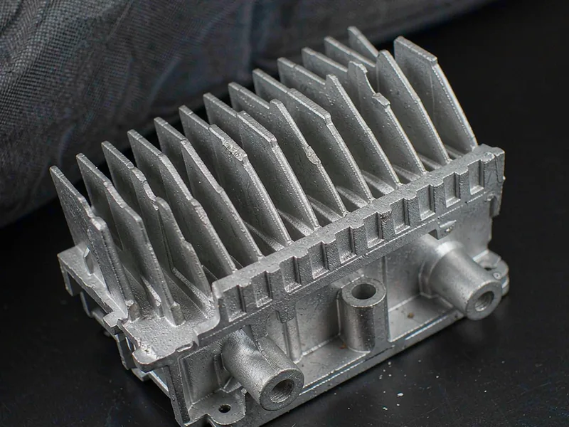
The table below lists typical as-cast values we work with. Treat them as realistic midpoints for well-made castings, not guaranteed minimums. Your supplier should confirm values for the actual heat and temper.
| Alloy | Silicon, % | Conductivity, W/m·K | Best suited for |
|---|---|---|---|
| A380 / ADC12 | 7.5–12 | ~96 | General housings with heat load |
| A360 | 9.5–10.5 | ~113 | Better heat spreading, corrosion zones |
| A413 | 11–13 | ~120 | Thin-wall, pressure-tight covers |
| AlSi10Mg | 9–10 | ~150 | High-power sinks, structural + thermal |
| 6061-T6 (wrought reference) | 0.4–0.8 | ~167 | Machined sinks, benchmark |
*Typical as-cast values at room temperature. Heat treatment, porosity, and impurity levels shift the real number by 10–20%.
Notice the spread. Moving from A380 to AlSi10Mg buys you more than 50 percent better conduction. For a compact LED driver or an inverter housing, that difference can drop junction temperatures several degrees without changing the geometry at all. This spread is why we design around measured cast aluminum thermal conductivity instead of alloy names alone.
Also notice what the table does not say. Datasheet values assume dense, clean metal. Real castings carry some porosity, and every percent of porosity drags conductivity down with it. Process quality is part of the thermal design.
Design Rules for Die Cast Heat Sinks
Die casting builds fins directly into the part, which is its biggest thermal advantage. But fins must eject from steel. Plan on a minimum fin thickness of about 2 mm at the tip, a draft of 1 to 1.5 degrees per side, and fin gaps no narrower than roughly 2.5 mm. Push harder and the fins misrun or the die wears early.
Aspect ratio is the next limit. Fins taller than about 10 to 12 times their thickness rarely fill well in standard die casting. If your thermal model wants tall, thin fins, consider a bonded or skived fin solution and let the casting carry the base and the interface.
Think about the whole path, not just the fins. Heat leaves the source through the base, spreads across it, then climbs the fins. A thick, well-fed base often helps more than extra fin area. Keep mounting bosses away from hot zones, and core them so they do not become thermal bottlenecks or shrink sinks.
Surface finish counts too. Cast skin and oxide films add contact resistance at interfaces. Machining the mounting pad flat and specifying a sensible flatness callout usually matters more than choosing between two alloys.
Cast vs Extruded vs Machined: A Fair Comparison
Extruded sinks conduct better per kilogram because 6061 alloy runs near 167 W/m·K and the fins are dense and thin. But extrusion limits the shape. The profile must be constant, and bosses, holes, and mounting features all need extra machining.
Die casting trades some conductivity for geometry. One shot gives you fins, enclosure walls, screw bosses, and connectors in place. In practice, cast aluminum thermal conductivity between 96 and 150 W/m·K covers most housing work comfortably. For a complete housing with integrated cooling, casting often wins on total cost even though the alloy conducts 30 to 40 percent less.
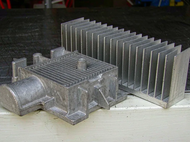
Machined sinks from wrought plate top the conductivity table but waste the most metal and machine time. They make sense for prototypes, very high flux densities, or small complex shapes where every watt matters.
A practical hybrid exists too. Cast the housing for integration, then press or bond a high-conductivity fin field into a machined pocket. Many power electronics packages use exactly this split, and it lets each process do what it does best.
How We Verify Thermal Performance
We start with chemistry, because it predicts the rest. Every heat gets a spectrometer reading, and we track iron and copper tightly on thermal grades since both depress conductivity. Density testing catches gas and shrink porosity before it hides in the fins.
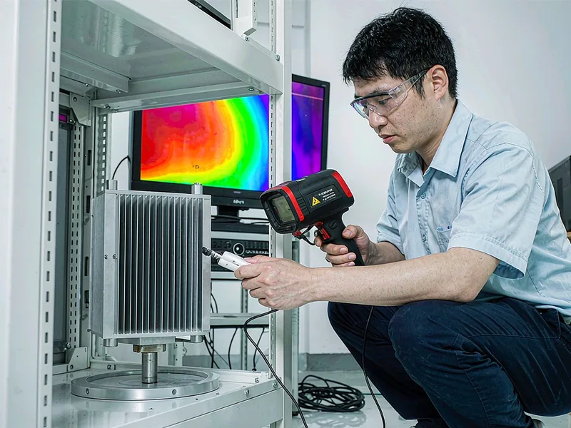
For critical programs we measure, not assume. Laser flash analysis on samples cut from actual castings gives a true conductivity number, and thermal imaging during bench tests shows how the real part spreads heat. These checks turn the datasheet into evidence.
Finally, we review the design with you. Send the heat load, the airflow, and the interface constraints. We will recommend an alloy, flag the fin geometry that will fill, and quote the part with realistic thermal numbers you can defend to your customer.
External Links
- ASTM B85 — standard specification for aluminum-alloy die castings, listing the chemistries behind each conductivity value.
- ASM International — authoritative handbooks on aluminum alloy thermal and physical property data.
- North American Die Casting Association (NADCA) — design guidance for die cast heat sinks, fin geometry, and thermal management housings.
FAQ
What is a good cast aluminum thermal conductivity for heat sinks?
Around 96 W/m·K for A380 and ADC12, about 113 for A360, and up to 150 for AlSi10Mg. Most electronics housings work well at 100 W/m·K or above when the fin design is sound.
Why is die cast aluminum less conductive than 6061?
Die casting alloys carry 9 to 12 percent silicon plus iron and copper for castability and die life. Those alloying atoms scatter the electrons that carry heat, so conductivity drops versus low-alloy wrought 6061.
Does heat treatment change thermal conductivity?
Yes. Aging moves alloying elements out of solid solution into precipitates, which usually raises conductivity slightly. Solution treating and quenching can lower it. Always compare values at the same temper.
How does porosity affect heat transfer?
Pores act like tiny insulators in the heat path. Gas porosity near the base or under the mounting pad hurts most, because it adds resistance right where heat flux is highest. Good degassing and die design limit the damage.
Can die casting make fins thin enough for cooling?
For most products, yes. Plan on 2 mm minimum fin thickness with draft, and fin aspect ratios up to about 10 to 12. For thinner, denser fins, bond or skive fins onto a cast base instead.